
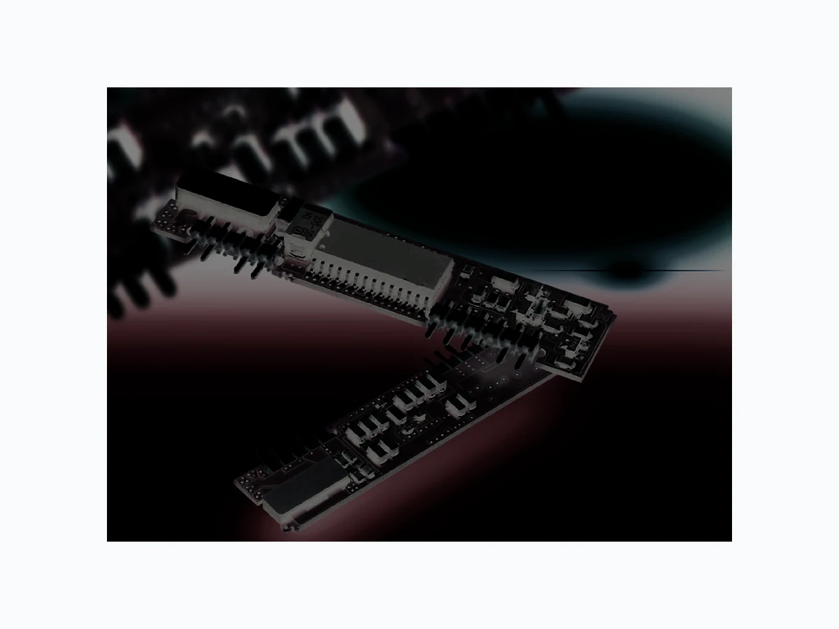
TL2105PIS POWER-ONE
Document overview
- Manufacturer or author: Provided By www.digicamel.com(FREE DATASHEET DOWNLOAD SITE)
- PDF pages: 2
Technical content
High Density - Board Mounted Power Division Rev. April 5, 2001 Powering Communications and Technology SIP502.5 10 20 30 40 50 60 70 80 90 100 LOAD % EFFICIENCY % EFF. (4.5v) EFF. (5v) EFF. (5.5v) SIP/SIE 500 NON-ISOLATED SERIES SIP/SIE non-isolated step-down DC/DC converters deliver high efficiency and excellent transient response in an industry standard SIP package. The SIP/SIE series has output voltages ranging from 1.2 to 3.3V and up to 6 amps of output current. The SIE model has power OK and remote sense pins for added flexibility and improved point of load regulation. The SIP/SIE series is available for vertical or horizontal mounting. The SIP/SIE series use 100% surface-mount construction for maximum reliability and feature over seven million hours MTBF.
- Non-Isolated
- High Efficiency Topology
- Excellent Transient Response
- Sense and Power OK (SIE Model Only)
DESCRIPTION
FEATURES
- Surface-Mount Construction
- Voltage Trim
- Vertical or Horizontal Mounting
- Water Washable Remote Shutdown Negative Logic Switching Frequency 350 KHz Temperature Coefficient 0.03% /°C Ambient Operating Temperature 0 to +55°C Minimum Required Airflow 200 LFM Storage Range -25 to +120°C Humidity Max., Non-Condensing 95% Vibration, 3 Axes, 5 Min Each 5 g, 10 - 55 Hz MTBF† (Bellcore TR-NWT-000332) 7.1 x 10 6 hrs Safety UL, cUL, TUV Weight (approx.) 0.25 oz Efficiency vs. Load Setpoint Accuracy ±1% Line Regulation Vin Min. - Vin Max., Iout Rated 1% V out Load Regulation Iout Min.- Iout Max., Vin Nom. 1% V out Ripple and Noise, DC - 20 MHz 50 mV Pk-Pk Remote Sense Headroom 0.25 V Current Limit Protection Type Hiccup Current Limit Threshold Range, % of I out Rated 150% Short Circuit Protection Type Latching Power Good Signal (SIE model only); Asserts “High” When Vout is Between the Following Thresholds: Lower Sense Threshold, % Vsetpoint -16% to -10% Upper Sense Threshold, % Vsetpoint +10% to +16% Power Good Signal Reference Common Ground Vout Ramp Up Rate, Minimum 0.5V/ms Notes † MTBF predictions may vary slightly from model to model. Specifications typically at 25°C, normal line, and full load, unless otherwise stated. Soldering Conditions: I/O pins, 260°C, ten seconds; fully compatible with commercial wave-soldering equipment. Safety: Agency approvals may vary from model to model. Please consult factory for specific model information. Units are water-washable and fully compatible with commercial spray or immersion post wave-solder washing equipment. TECHNICAL SPECIFICATIONS Voltage Range 5 VDC Nominal 4.5 - 5.5 VDC Input Output General
Powering Communications and Technology SIP/SIE 500 NON-ISOLATED SERIES 0.25 (6.40) 0.11 (2.80) 0.025 (0.64) SQ. 0.09 (2.30) 0.13 (3.30) 0.27 (6.90) 0.55 (14.0) 1234 5 6789 1 0 1 1 0.100 (2.54) TYP. 0.28 (7.10) 1.90 (48.26) 2.50 (63.5) Right Angle Pins 0.55 (14.0) 1.90 (48.26) 2.50 (63.5) 0.28 (7.10) 0.100 (2.54) TYP. 0.13 (3.30) 0.025 (0.64) SQ. 12345 6 7 8 9 10 11 Natural Convection 24.4 °C/W 100 LFM 18.3 °C/W 200 LFM 15.0 °C/W 300 LFM 11.1 °C/W 400 LFM 7.9 °C/W Note: Thermal impedance data is dependent on many environmental factors. The exact thermal performance should be validated for specific application. 12 3 4 5 67 8 91 0 1 1 2.50 (63.5) 1.90 (48.26) 0.13 (3.30) 0.55 (14.0) 0.10 (2.54) TYP. 0.025 (0.64) SQ. 0.28 (7.10) 0.55 (14.0) 1.90 (48.26) 2.50 (63.5) 0.10 (2.54) TYP. 0.28 (7.10) 12 3 4 5 67 89 1 0 1 1 0.025 (0.64) SQ. 0.09 (2.30) 0.13 (3.30) 0.27 (6.90) 0.25 (6.40) 0.11 (2.80) Right Angle Pins MECHANICAL DRAWING Inches: (Millimeters) Pin: ± 0.002 ± 0.05 (Dimensions as listed unless otherwise specified.) MODELS - (See the last page of Section for options.) 1+ V out 2+ V out
3 Sense (SIE)
5 Ground
6 Ground
9 PWR OK (SIE)
10 Trim
11 Enable
t r a h C n o i t c e l e S l e d o M n i V ) s t l o V ( e g n a R n i V ) s t l o V ( * . x a M n i I ) s p m A ( t u o V ) s t l o V ( d e t a R t u o I ) s p m A ( y c n e i c i f f E * * . p y T T L 2 . 1 0 5 P I S T L 5 . 1 0 5 P I S T L 8 . 1 0 5 P I S T L 1 . 2 0 5 P I S T L 5 . 2 0 5 P I S T L 3 . 3 0 5 P I S T L 2 . 1 0 5 E I S T L 5 . 1 0 5 E I S T L 8 . 1 0 5 E I S T L 1 . 2 0 5 E I S T L 5 . 2 0 5 E I S T L 3 . 3 0 5 E I S 5 . 5 - 5 . 4 5 . 5 - 5 . 4 5 . 5 - 5 . 4 5 . 5 - 5 . 4 5 . 5 - 5 . 4 5 . 5 - 5 . 4 5 . 5 - 5 . 4 5 . 5 - 5 . 4 5 . 5 - 5 . 4 5 . 5 - 5 . 4 5 . 5 - 5 . 4 5 . 5 - 5 . 4 3 . 2 7 . 2 1 . 3 5 . 3 0 . 4 1 . 5 3 . 2 7 . 2 1 . 3 5 . 3 0 . 4 1 . 5 2 . 1 5 . 1 8 . 1 1 . 2 5 . 2 3 . 3 2 . 1 5 . 1 8 . 1 1 . 2 5 . 2 3 . 3 % 0 7 % 5 7 % 7 7 % 1 8 % 3 8 % 7 8 % 0 7 % 5 7 % 7 7 % 1 8 % 3 8 % 7 8 . r e w o p t u p t u o d e t a r m u m i x a m , e g a t l o v t u p n i m u m i n i m t a t n e r r u c t u p n i m u m i x a M * . t u p t u o d e t a r , n i V l a n i m o n t A * * . r e b m u n l e d o m o t " R " x i f f u s d d A , s n i P e l g n A t h g i R r o F : E T O N SIE MODELSIP MODEL Tolerances High Density - Board Mounted Power Division Thermal Impedance Pin Function