
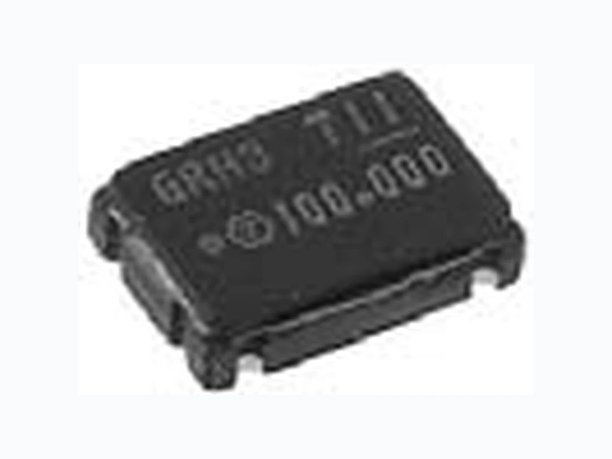
TFG-786XH ETC1
Document overview
- Manufacturer or author: Provided By www.digicamel.com(FREE DATASHEET DOWNLOAD SITE)
- PDF pages: 1
Technical content
Features
Small size : 7.0(W) X 5.0(D) X 2.0(H)mm One chip PLL with VCO Low operation voltage (+3.3V & +5.0V) Parameter TFG-786RH 0 °C to +70 °C See Table A (max.) VIH=70% Vcc min. / VIL=20% Vcc max. VOH=90% Vcc min. / VOL=10% Vcc max. 45 to 55 % 3 ns max. 30 pF max. 15 pF max. 2 ms max. Frequency Frequency Stability Operating Temperature Supply Voltage Supply Current Input Voltage Output Voltage Symmetry Rise/Fall time Load Capacitance Start-up time fo Δf/fo Topr Vcc Icc VIH VIL VOH VOL SYM tr/tf CL tst TFG-787RH3 Conditions ±100 ppm max. ±50 ppm max. (*1) DC Vcc=+5.5V or +3.6V #1:VIH or OPEN ... Enable #1:VIL or GND ... Disable IOH=-4mA, IOL=+4mA at Vcc=+4.5V IOH=-2.4mA, IOL=+2.4mA at Vcc=+3.0V at 50% Vcc at 20% to 80% Vcc 70 < fo ≤ 120 MHz 120 < fo ≤ 140 MHz (*2) 70 to 140 MHz 70 to 112 MHz +3.3 V ±10 % TFG-786XH +3.3 V ±10 % *1 Inclusive of calibration tolerance at +25°C, operating temperature, operating voltage range. *2 Rise time (0 to +4.5V or +3.0V) of Vcc >150μs Table A LEAD CONNECTION E/D CONTROL GND OUTPUT Vcc (DC) 7.0±0.2 5.08±0.15 1.1±0.15 1.0±0.15 5.0±0.21.8±0.2 #4 #3 #1 #2 MODEL FREQUENCY DENOTES LEAD#1 LOCATION DATE CODE Marking Cby=0.1μF min. 1.8 5.08 4.2 2.0 Cby #3#4 Test Circuit See Test Circuit page TEST -4 Footprint [Dimensions in mm] (2001. 2.) 70 < fo fo ≤ 96 Freq. (MHz) Icc (mA) 96 < fo fo ≤ 120 120 < fo fo ≤ 140 Vcc 60 70 60 at +5.5V 40 50 50 at +3.6V