
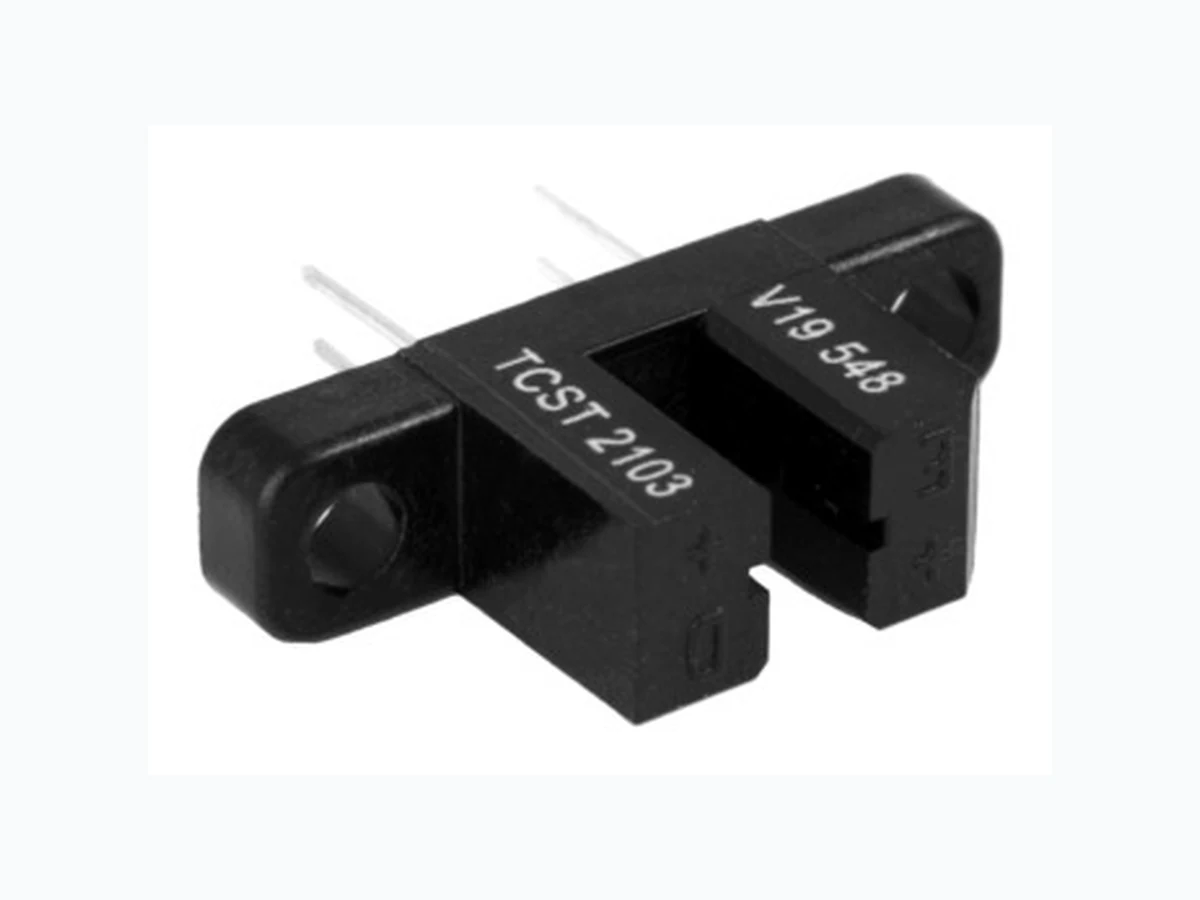
TCST2103_09 VISHAY
Document overview
- Manufacturer or author: Provided By www.digicamel.com(free datasheet download site)
- PDF pages: 12
Technical content
Document Number: 81147 For technical questions, contact: sensorstechsupport@vishay.com www.vishay.com Rev. 1.0, 17-Aug-09 1 Transmissive Optical Sensor with Phototransistor Output TCST2103, TCST2202, TCST2300 Vishay Semiconductors
DESCRIPTION
The TCST2103, TCST2202, and TCST2300 are transmissive sensors that incl ude an infrared emitter and phototransistor, located face-to-face on the optical axes in a leaded package which blocks visible light. These part numbers include options for aperture width.
FEATURES
- Package type: leaded Detector type: phototransistor Dimensions (L x W x H in mm): 24.5 x 6.3 x 10.8 Gap (in mm): 3.1 Typical output current under test: I C = 4 mA (TCST2103) Typical output cu rrent under test: IC = 2 mA (TCST2202) Typical output current under test: IC = 0.5 mA (TCST2300) Daylight blocking filter Emitter wavelength: 950 nm Lead (Pb)-free soldering released Compliant to RoHS directive 2002/95/EC and in accordance to WEEE 2002/96/EC
APPLICATIONS
Optical switch Photo interrupter Counter Encoder Note (1) Conditions like in table basic characteristics/coupler Note (1) MOQ: minimum order quantity 19180_3 Top view D 7.6 mm 0.3" 19180_4 PRODUCT SUMMARY PART NUMBER GAP WIDTH (mm) APERTURE WIDTH (mm) TYPICAL OUTPUT CURRENT UNDER TEST (1) (mA) DAYLIGHT BLOCKING FILTER INTEGRATED TCST2103 3.1 1 4 Yes TCST2202 3.1 0.5 2 Yes TCST2300 3.1 0.25 0.5 Yes
ORDERING INFORMATION
VOLUME (1) REMARKS TCST2103 Tube MOQ: 1020 pcs, 85 pcs/tube With mounting flange TCST2202 Tube MOQ: 1020 pcs, 85 pcs/tube With mounting flange TCST2300 Tube MOQ: 1020 pcs, 85 pcs/tube With mounting flange ABSOLUTE MAXIMUM RATINGS (1) PARAMETER TEST CONDITION SYMBOL VALUE UNIT COUPLER Total power dissipation T amb ≤ 25 °C P tot 250 mW Ambient temperature range T amb - 55 to + 85 °C Storage temperature range T stg - 55 to + 100 °C Soldering temperature Distance to package: 2 mm; t ≤ 5 s T sd 260 °C
www.vishay.com For technical questions, contact: sensorstechsupport@vishay.com Document Number: 81147 2 Rev. 1.0, 17-Aug-09 TCST2103, TCST2202, TCST2300 Vishay Semiconductors Transmissive Optical Sensor with Phototransistor Output Note (1) Tamb = 25 °C, unless otherwise specified ABSOLUTE MAXIMUM RATINGS Fig. 1 - Power Dissipation Limit vs. Ambient Temperature INPUT (EMITTER) Reverse voltage V R 6V Forward current I F 60 mA Forward surge current t p ≤ 10 µs I FSM 3A Power dissipation T amb ≤ 25 °C P V 100 mW Junction temperature T j 100 °C OUTPUT (DETECTOR) Collector emitter voltage V CEO 70 V Emitter collector voltage V ECO 7V Collector peak current t p/T = 0.5, tp ≤ 10 ms I CM 200 mA Power dissipation T amb ≤ 25 °C P V 150 mW Junction temperature T j 100 °C ABSOLUTE MAXIMUM RATINGS (1) PARAMETER TEST CONDITION SYMBOL VALUE UNIT 100 200 300 400 95 11088 P - Power Dissipation (mW) T amb - Ambient Tem p erature Coupled device Phototransistor IR-diode 150 120 90 60 30 BASIC CHARACTERISTICS (1) PARAMETER TEST CONDITION PART SYMBOL MIN. TYP. MAX. UNIT COUPLER Current transfer ratio V CE = 5 V, IF = 20 mA TCST2103 CTR 10 20 % TCST2202 CTR 5 10 % TCST2300 CTR 1.25 2.5 % Collector current V CE = 5 V, IF = 20 mA TCST2103 I C 24 m A TCST2202 I C 12 m A TCST2300 I C 0.25 0.5 mA Collector emitter saturation voltage IF = 20 mA, IC = 1 mA TCST2103 V CEsat 0.4 V IF = 20 mA, IC = 0.5 mA TCST2202 V CEsat 0.4 V IF = 20 mA, IC = 0.1 mA TCST2300 V CEsat 0.4 V Resolution, path of the shutter crossing the radiant sensitive zone I Crel = 10 % to 90 % TCST2103 s 0.6 mm TCST2202 s 0.4 mm TCST2300 s 0.2 mm
Document Number: 81147 For technical questions, contact: sensorstechsupport@vishay.com www.vishay.com Rev. 1.0, 17-Aug-09 3 TCST2103, TCST2202, TCST2300 Transmissive Optical Sensor with Phototransistor Output Vishay Semiconductors Note (1) Tamb = 25 °C, unless otherwise specified Fig. 2 - Test Circuit for ton and toff Fig. 3 - Switching Times BASIC CHARACTERISTICS Tamb = 25 °C, unless otherwise specified Fig. 4 - Forward Current vs. Forward Voltage Fig. 5 - Re lative Current Transfer Ratio vs. Ambient Temperature INPUT (EMITTER) Forward voltage I F = 60 mA V F 1.25 1.6 V Junction capacitance V R = 0 V, f = 1 MHz C j 50 pF OUTPUT (DETECTOR) Collector emitter voltage I C = 1 mA V CEO 70 V Emitter collector voltage I E = 10 µA V ECO 7V Collector dark current V CE = 25 V, IF = 0 A, E = 0 lx I CEO 100 nA SWITCHING CHARACTERISTICS Turn-on time IC = 2 mA, VS = 5 V, RL = 100 Ω (see figure 2) ton 10 µs Turn-off time IC = 2 mA, VS = 5 V, RL = 100 Ω (see figure 2) toff 8µ s BASIC CHARACTERISTICS (1) PARAMETER TEST CONDITION PART SYMBOL MIN. TYP. MAX. UNIT Channel I Channel II 20688 + 5 V IC adjusted by IF IF IF RG = 50 Ω tp tp = 1 ms T = 20 Oscilloscope 50 Ω 100 Ω R L ≥ 1 MΩ CL ≤ 20 pF t p t t 10 % 90 % 100 % tr td ton ts tf toff IF IC tp Pulse duration td Delay time tr Rise time ton (= td + tr) T urn-on time ts Storage time t f Fall time toff (= ts + tf)T urn-off time 96 11698 0.1 100 1000 VF - Forward Voltage (V)96 11862 IF - Forward Current (mA) - 25 0.5 1.0 1.5 2.0 CTR - Relative Current Transfer Ratiorel T amb - Ambient Temperature (°C) 95 11089 V CE = 5 V I F = 20 mA 10075 50 25 0
www.vishay.com For technical questions, contact: sensorstechsupport@vishay.com Document Number: 81147 4 Rev. 1.0, 17-Aug-09 TCST2103, TCST2202, TCST2300 Vishay Semiconductors Transmissive Optical Sensor with Phototransistor Output Fig. 6 - Collector Dark Current vs. Ambient Temperature Fig. 7 - Collector Current vs. Forward Current Fig. 8 - Collector Current vs. Collector Emitter Voltage Fig. 9 - Current Transfer Ratio vs. Forward Current Fig. 10 - Turn-off/Turn-on Time vs. Collector Current Fig. 11 - Relative Collector Current vs. Displacement 100 1000 10 000 I - Collector Dark C urrent (nA)CEO T amb - Ambient Temperature (°C) 95 11090 V CE = 25 V I F = 0 A 100755025 0.001 0.01 0.1 0.1 I F - Forward Current (mA) 96 12066 VCE = 5 V I - Collector C urrent (mA) C 10010 1 0.01 0.1 0.1 V CE - Collector Emitter Voltage (V)96 12067 I - Collector Current (mA) C 20 mA 10 mA 5 mA 2 mA 1 mA I F = 50 mA 10010 1 0.1 100 0.1 I F - Forward Current (mA) 96 12068 V CE = 5 V CTR - Current Transfer Ratio (%) 10010 1 I C - Collector Current (mA) 95 11086 t t - T urn on Turn off Time (µs) off on Non saturated operation V S = 5 V R L = 100 Ω t on t off 108642 100 110 - 0.5 s - Displacement (mm) 96 12005 I - Relati ve Collector CurrentCrel s A = 1 mm
Document Number: 81147 For technical questions, contact: sensorstechsupport@vishay.com www.vishay.com Rev. 1.0, 17-Aug-09 5 TCST2103, TCST2202, TCST2300 Transmissive Optical Sensor with Phototransistor Output Vishay Semiconductors Fig. 12 - Relative Collector Current vs. Displacement Fig. 13 - Relative Collector Current vs. Displacement PACKAGE DIMENSIONS in millimeters 96 12006 s A = 0.5 mm 100 110 - 0.5 s - Dis p lacement mm I - Relative Collector CurrentCrel 96 12007 s A = 0.25 mm 100 110 - 0.5 s - Displacement (mm) I - Relati ve Collector CurrentCrel 96 12095 Drawing-No.: 6.550-5040.01-4 Issue: 2; 10.11.98
www.vishay.com For technical questions, contact: sensorstechsupport@vishay.com Document Number: 81147 6 Rev. 1.0, 17-Aug-09 TCST2103, TCST2202, TCST2300 Vishay Semiconductors Transmissive Optical Sensor with Phototransistor Output TUBE DIMENSIONS in millimeters 20252
Document Number: 80112 For technical questions, contact: optocoupleranswers@vishay.com www.vishay.com Rev. 1.1, 02-Jul-09 1 Packaging and Ordering Information Packaging and Ordering Information Vishay Semiconductors Notes (1) MOQ: minimum order quantity (2) Please refer to datasheets TUBE SPECIFICATION FIGURES Fig. 1 PART NUMBER MOQ (1) PCS PER TUBE TUBE SPEC. (FIGURE) CONSTITUENTS (FORMS) CNY70 4000 80 1 28 TCPT1300X01 2000 Reel (2) 29 TCRT1000 1000 Bulk - 26 TCRT1010 1000 Bulk - 26 TCRT5000 4500 50 2 27 TCRT5000L 2400 48 3 27 TCST1030 5200 65 5 24 TCST1030L 2600 65 6 24 TCST1103 1020 85 4 24 TCST1202 1020 85 4 24 TCST1230 4800 60 7 24 TCST1300 1020 85 4 24 TCST2103 1020 85 4 24 TCST2202 1020 85 4 24 TCST2300 1020 85 4 24 TCST5250 4860 30 8 24 TCUT1300X01 2000 Reel (2) 29 TCZT8020-PAER 2500 Bulk - 22 15198
www.vishay.com For technical questions, contact: optocoupleranswers@vishay.com Document Number: 80112 2 Rev. 1.1, 02-Jul-09 Packaging and Ordering Information Vishay Semiconductors Packaging and Ordering Information Fig. 2 Fig. 3 15210 15201
Document Number: 80112 For technical questions, contact: optocoupleranswers@vishay.com www.vishay.com Rev. 1.1, 02-Jul-09 3 Packaging and Ordering Information Packaging and Ordering Information Vishay Semiconductors Fig. 4 Fig. 5 15199 15202
www.vishay.com For technical questions, contact: optocoupleranswers@vishay.com Document Number: 80112 4 Rev. 1.1, 02-Jul-09 Packaging and Ordering Information Vishay Semiconductors Packaging and Ordering Information Fig. 6 Fig. 7 15196 15195
Document Number: 80112 For technical questions, contact: optocoupleranswers@vishay.com www.vishay.com Rev. 1.1, 02-Jul-09 5 Packaging and Ordering Information Packaging and Ordering Information Vishay Semiconductors Fig. 8 20257
Document Number: 91000 www.vishay.com Revision: 11-Mar-11 1 Disclaimer Legal Disclaimer Notice Vishay ALL PRODUCT, PRODUCT SPECIFICATIONS AND DATA AR E SUBJECT TO CHANGE WITHOUT NOTICE TO IMPROVE RELIABILITY, FUNCTION OR DESIGN OR OTHERWISE. Vishay Intertechnology, Inc., its affiliates, agents, and employees, and all persons acting on its or their behalf (collectivel y, “Vishay”), disclaim any and all liability for any errors, inaccuracies or incompleteness contained in any datasheet or in any other disclosure relating to any product. Vishay makes no warranty, representation or guarantee regarding the suitability of the products for any particular purpose or the continuing production of any product. To the maximum extent permitted by applicable law, Vishay disclaims (i) any and all liability arising out of the application or use of any product, (ii) any and all liability, incl uding without limitation specia l, consequential or incidental dama ges, and (iii) any and all impl ied warranties, including warran ties of fitness for particular purpose, non-infringement and merchantability. Statements regarding the suitability of pro ducts for certain types of applications are based on Vishay’s knowledge of typical requirements that are often placed on Vishay products in gene ric applications. Such statements are not binding statements about the suitability of products for a partic ular application. It is the customer’s responsibility to validate that a particu lar product with the properties described in th e product specification is su itable for use in a particul ar application. Parameters provided in datasheets an d/or specifications may vary in different applications and perfo rmance may vary over time. All operating parameters, including typical pa rameters, must be validated for each customer application by the customer’s technical experts. Product specifications do not expand or otherwise modify Vishay’s term s and conditions of purchase, including but not limited to the warranty expressed therein. Except as expressly indicated in writing, Vishay products are not designed for use in medical, life-saving, or life-sustaining applications or for any other application in which the failure of the Vishay product co uld result in person al injury or death. Customers using or selling Vishay products not expressly indicated for use in such applications do so at their own risk and agree to fully indemnify and hold Vishay and it s distributors harmless from and against an y and all claims, liabilities, expenses and damages arising or resulting in connection with such use or sale, including attorneys fees, even if such claim alleges that Vishay or its distributor was negligent regarding the design or manufacture of the part. Please contact authorized Vishay personnel to obtain written terms and conditions regarding products designed for such applications. No license, express or implied, by estoppel or otherwise, to any intellectual property rights is granted by this document or by any conduct of Vishay. Product names and markings noted herein may be trademarks of their respective owners.