
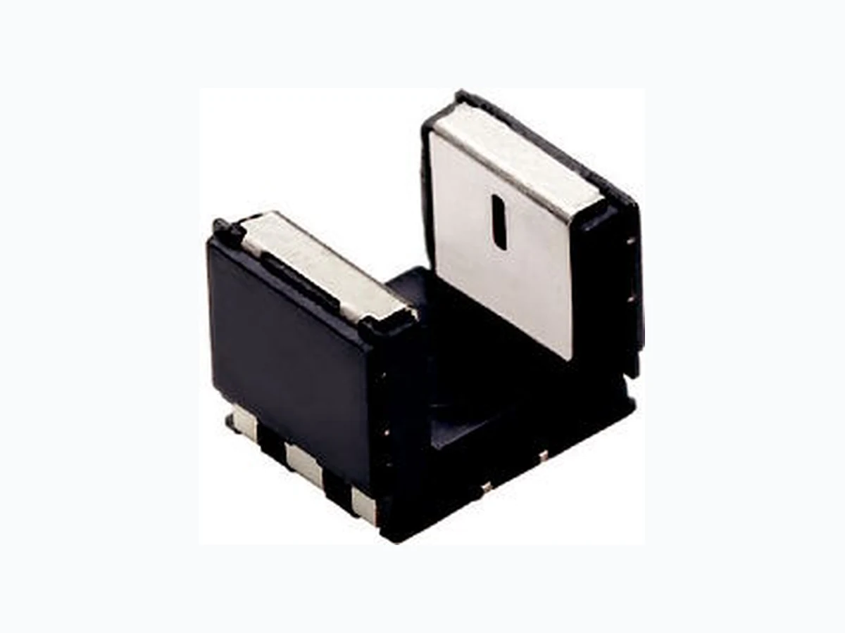
TCPT1350X01 VISHAY
Document overview
- Manufacturer or author: Provided By www.digicamel.com(free datasheet download site)
- PDF pages: 13
Technical content
www.vishay.com Vishay Semiconductors Rev. 1.0, 14-Mar-13 1 Document Number: 84815 For technical questions, contact: sensorstechsupport@vishay.com THIS DOCUMENT IS SUBJECT TO CHANGE WITHOUT NOTICE. THE PRODUCTS DESCRIBED HEREIN AND THIS DOCUMENT ARE SUBJECT TO SPECIFIC DISCLAIMERS, SET FORTH AT www.vishay.com/doc?91000 Subminiature Transmissive Optical Sensor with Transistor Output
DESCRIPTION
The TCPT1350X01 is a compact transmissive sensor that includes an infrared emitter and a phototransistor detector, located face-to-face in a surface mount package. TCPT1350X01 is especially designed to meet high operating temperature requirements and is released for operating temperature ranges from - 40 °C to + 125 °C.
FEATURES
- Package type: surface mount
- Detector type: phototransistor
- Dimensions (L x W x H in mm): 5.5 x 4 x 4
- AEC-Q101 qualified
- Gap (in mm): 3
- Aperture (in mm): 0.3
- Typical output current under test: I C = 1.6 mA
- Emitter wavelength: 950 nm
- Released for high operating temperatures up to 125 °C
- Moisture sensitivity level (MSL): 1
- Material categorization: For definitions of compliance please see www.vishay.com/doc?99912
APPLICATIONS
- Automotive optical sensors
- Accurate position sensor for encoder
- Detection of motion speed Note
- Conditions like in table basic characteristics/coupler Note
- MOQ: minimum order quantity Pin connection Top view Coll. NC E A Cath. NC 21848 19601 PRODUCT SUMMARY PART NUMBER GAP WIDTH (mm) APERTURE WIDTH (mm) TYPICAL OUTPUT CURRENT UNDER TEST (1) (mA) DAYLIGHT BLOCKING FILTER INTEGRATED TCPT1350X01 3 0.3 1.6 No
ORDERING INFORMATION
ORDERING CODE PACKAGING VOLUME (1) REMARKS TCPT1350X01 Tape and reel MOQ: 2000 pc s, 2000 pcs/reel Drypack, MSL 1
www.vishay.com Vishay Semiconductors Rev. 1.0, 14-Mar-13 2 Document Number: 84815 For technical questions, contact: sensorstechsupport@vishay.com THIS DOCUMENT IS SUBJECT TO CHANGE WITHOUT NOTICE. THE PRODUCTS DESCRIBED HEREIN AND THIS DOCUMENT ARE SUBJECT TO SPECIFIC DISCLAIMERS, SET FORTH AT www.vishay.com/doc?91000 ABSOLUTE MAXIMUM RATINGS Fig. 1 - Power Dissipation Limit vs. Ambient Temperature Fig. 2 - Forward Current Limit vs. Ambient Temperature ABSOLUTE MAXIMUM RATINGS (Tamb = 25 °C, unless otherwise specified) PARAMETER TEST CONDITION SYMBOL VALUE UNIT COUPLER Total power dissipation T amb 125 °C P tot 37.5 mW Junction temperature T j 140 °C Ambient temperature range T amb - 40 to + 125 °C Storage temperature range T stg - 40 to + 125 °C Soldering temperature In accordance with fig. 16 T sd 260 °C INPUT (EMITTER) Reverse voltage V R 5V Forward current T amb 125 °C I F 25 mA Forward surge current t p 10 μs I FSM 200 mA Power dissipation T amb 125 °C P V 37.5 mW OUTPUT (DETECTOR) Collector emitter voltage V CEO 20 V Emitter collector voltage V ECO 7V Collector current I C 20 mA Collector dark current T amb 85 °C, VCE = 5 V I CEO 3.3 μA 0 20 40 60 80 100 140 PV - Power Dissipation (mW) Tamb - Ambient Temperature (°C) RthJA = 460 K/W 120 0 20 40 60 80 100 140 IF - Forward Current (mA) Tamb - Ambient Temperature (°C) RthJA = 460 K/W 120
www.vishay.com Vishay Semiconductors Rev. 1.0, 14-Mar-13 3 Document Number: 84815 For technical questions, contact: sensorstechsupport@vishay.com THIS DOCUMENT IS SUBJECT TO CHANGE WITHOUT NOTICE. THE PRODUCTS DESCRIBED HEREIN AND THIS DOCUMENT ARE SUBJECT TO SPECIFIC DISCLAIMERS, SET FORTH AT www.vishay.com/doc?91000 Fig. 3 - Test Circuit for tr and tf Fig. 4 - Switching Times BASIC CHARACTERISTICS (Tamb = 25 °C, unless otherwise specified) Fig. 5 - Forward Current vs. Forward Voltage Fig. 6 - Forward Voltage vs. Ambient Temperature BASIC CHARACTERISTICS (Tamb = 25 °C, unless otherwise specified) PARAMETER TEST CONDITION SYMBOL MIN. TYP. MAX. UNIT COUPLER Collector current V CE = 5 V, IF = 15 mA I C 0.7 1.6 mA Collector emitter saturation voltage IF = 15 mA, IC = 0.2 mA V CEsat 0.4 V INPUT (EMITTER) Forward voltage I F = 15 mA V F 11 . 2 1 . 4V Reverse current V R = 5 V I R 10 μA Junction capacitance V R = 0 V, f = 1 MHz C j 25 pF OUTPUT (DETECTOR) Collector emitter voltage I C IC = 1 mA V CEO 20 V Emitter collector voltage I E = 100 μA V ECO 7V Collector dark current V CE = 25 V, IF = 0 A, E = 0 lx I CEO 1 100 nA SWITCHING CHARACTERISTICS Rise time I C = 0.7 mA, VCE = 5 V, RL = 100 (see figure 3) tr 9 150 μs Fall time IC = 0.7 mA, VCE = 5 V, RL = 100 (see figure 3) tf 16 150 μs Channel I Channel II 20688 + 5 V IC adjusted by IF IF IF RG = 50 Ω tp tp = 1 ms T = 20 Oscilloscope 50 Ω 100 Ω R L ≥ 1 MΩ CL ≤ 20 pF t p t t 10 % 90 % 100 % tr td ton ts tf toff IF IC tp Pulse duration td Delay time tr Rise time ton (= td + tr) Turn-on time ts Storage time t f Fall time toff (= ts + tf) Turn-off time 96 11698 100 VF - Forward Voltage (V) IF - Forward Current (mA) 20589 22680 1.0 1.1 1.2 1.3 1.4 - 50 - 25 0 25 50 75 100 150 Tamb - Ambient Temperature (°C) VF - Forward Voltage (V) 125
www.vishay.com Vishay Semiconductors Rev. 1.0, 14-Mar-13 4 Document Number: 84815 For technical questions, contact: sensorstechsupport@vishay.com THIS DOCUMENT IS SUBJECT TO CHANGE WITHOUT NOTICE. THE PRODUCTS DESCRIBED HEREIN AND THIS DOCUMENT ARE SUBJECT TO SPECIFIC DISCLAIMERS, SET FORTH AT www.vishay.com/doc?91000 Fig. 7 - Collector Current vs. Forward Current Fig. 8 - Collector Current vs. Collector Emitter Voltage Fig. 9 - Collector Emitter Saturation Voltage vs. Ambient Temperature Fig. 10 - Collector Current vs. Ambient Temperature Fig. 11 - Collector Dark Current vs. Ambient Temperature Fig. 12 - Relative Collector Current vs. Horizontal Displacement 22681 0.01 0.1 1 10 100 IF - Forward Current (mA) IC - Collector Current (mA) VCE = 5 V 0.01 0.1 0.1 1 10 100 VCE - Collector Emitter Voltage (V) IC - Collector Current (mA) 22682 IF = 25 mA IF = 15 mA IF = 5 mA IF = 3 mA 0.00 0.05 0.10 0.15 0.20 0.25 0.30 - 50 - 25 0 25 50 75 125 150 Tamb - Ambient Tempearture (°C) VCEsat - Coll. Emitter Saturation Voltage (V) IF = 15 mA IF = 5 mA IC = 200 μA 22683 100 0.0 0.5 1.0 1.5 2.0 2.5 - 50 - 25 0 25 50 100 125 150 Tamb - Ambient Temperature (°C) IC - Collector Current (mA) 22684 IF = 15 mA IF = 5 mA VCE = 5 V 100 1000 100 000 - 50 - 25 0 25 50 75 100 125 150 Tamb - Ambient Temperature (°C) ICEO - Collector Dark Current (nA) 22685 VCE = 70 V VCE = 25 V VCE = 5 V 10 000 0.2 0.4 0.6 0.8 S - Horizontal Displacement (mm) IC rel - Relative Collector Current 20595 S
www.vishay.com Vishay Semiconductors Rev. 1.0, 14-Mar-13 5 Document Number: 84815 For technical questions, contact: sensorstechsupport@vishay.com THIS DOCUMENT IS SUBJECT TO CHANGE WITHOUT NOTICE. THE PRODUCTS DESCRIBED HEREIN AND THIS DOCUMENT ARE SUBJECT TO SPECIFIC DISCLAIMERS, SET FORTH AT www.vishay.com/doc?91000 Fig. 13 - Relative Collector Current vs. Vertical Displacement Fig. 14 - Rise/Fall Time vs. Collector Current Fig. 15 - Application example REFLOW SOLDER PROFILE Fig. 16 - Lead (Pb)-free Reflow Solder Profile acc. J-STD-020 FLOOR LIFE No time limit. Moisture sensitivity level (MSL) 1, acc. JEDEC, J-STD-020. 0.5 S - Vertical Displacement (mm) ICrel - Rel. Collector Current 20610 S 1 ± 0.2 Optical axis 100 0 250 500 750 1000 1250 1500 1750 2000 I C - Collector Current (µA) tr/tf - Rise/Fall Time (µs) tf tr 20599 RL = 100 Ω 13887 74HCT14 GND IF = 15 mA + V C = 5 V 10 kΩ VE UQ 100 150 200 250 300 0 50 100 150 200 250 300 Time (s) Temperature (°C) 240 °C 245 °C max. 260 °C max. 120 s max. 100 s 217 °C max. 30 s max. ramp up 3 °C/s max. ramp down 6 °C/s 19841 255 °C
www.vishay.com Vishay Semiconductors Rev. 1.0, 14-Mar-13 6 Document Number: 84815 For technical questions, contact: sensorstechsupport@vishay.com THIS DOCUMENT IS SUBJECT TO CHANGE WITHOUT NOTICE. THE PRODUCTS DESCRIBED HEREIN AND THIS DOCUMENT ARE SUBJECT TO SPECIFIC DISCLAIMERS, SET FORTH AT www.vishay.com/doc?91000 PACKAGE DIMENSIONS in millimeters 19591
www.vishay.com Vishay Semiconductors Rev. 1.0, 14-Mar-13 7 Document Number: 84815 For technical questions, contact: sensorstechsupport@vishay.com THIS DOCUMENT IS SUBJECT TO CHANGE WITHOUT NOTICE. THE PRODUCTS DESCRIBED HEREIN AND THIS DOCUMENT ARE SUBJECT TO SPECIFIC DISCLAIMERS, SET FORTH AT www.vishay.com/doc?91000 PACKAGE DIMENSIONS in millimeters Volume/reel = 2000 pcs 20601
Document Number: 80112 For technical questions, contact: optocoupleranswers@vishay.com www.vishay.com Rev. 1.1, 02-Jul-09 1 Packaging and Ordering Information Packaging and Ordering Information Vishay Semiconductors Notes (1) MOQ: minimum order quantity (2) Please refer to datasheets TUBE SPECIFICATION FIGURES Fig. 1 PART NUMBER MOQ (1) PCS PER TUBE TUBE SPEC. (FIGURE) CONSTITUENTS (FORMS) CNY70 4000 80 1 28 TCPT1300X01 2000 Reel (2) 29 TCRT1000 1000 Bulk - 26 TCRT1010 1000 Bulk - 26 TCRT5000 4500 50 2 27 TCRT5000L 2400 48 3 27 TCST1030 5200 65 5 24 TCST1030L 2600 65 6 24 TCST1103 1020 85 4 24 TCST1202 1020 85 4 24 TCST1230 4800 60 7 24 TCST1300 1020 85 4 24 TCST2103 1020 85 4 24 TCST2202 1020 85 4 24 TCST2300 1020 85 4 24 TCST5250 4860 30 8 24 TCUT1300X01 2000 Reel (2) 29 TCZT8020-PAER 2500 Bulk - 22 15198
www.vishay.com For technical questions, contact: optocoupleranswers@vishay.com Document Number: 80112 2 Rev. 1.1, 02-Jul-09 Packaging and Ordering Information Vishay Semiconductors Packaging and Ordering Information Fig. 2 Fig. 3 15210 15201
Document Number: 80112 For technical questions, contact: optocoupleranswers@vishay.com www.vishay.com Rev. 1.1, 02-Jul-09 3 Packaging and Ordering Information Packaging and Ordering Information Vishay Semiconductors Fig. 4 Fig. 5 15199 15202
www.vishay.com For technical questions, contact: optocoupleranswers@vishay.com Document Number: 80112 4 Rev. 1.1, 02-Jul-09 Packaging and Ordering Information Vishay Semiconductors Packaging and Ordering Information Fig. 6 Fig. 7 15196 15195
Document Number: 80112 For technical questions, contact: optocoupleranswers@vishay.com www.vishay.com Rev. 1.1, 02-Jul-09 5 Packaging and Ordering Information Packaging and Ordering Information Vishay Semiconductors Fig. 8 20257
www.vishay.com Vishay Revision: 02-Oct-12 1 Document Number: 91000 Disclaimer ALL PRODUCT, PRODUCT SPECIFICATIONS AND DATA ARE SUBJECT TO CHANGE WITHOUT NOTICE TO IMPROVE RELIABILITY, FUNCTION OR DESIGN OR OTHERWISE. Vishay Intertechnology, Inc., its affiliates, agents, and employee s, and all persons acting on it s or their behalf (collectivel y, “Vishay”), disclaim any and all liability for any errors, inaccuracies or incompleteness contained in any datasheet or in any other disclosure relating to any product. Vishay makes no warranty, repres entation or guarantee regarding the suitabilit y of the products for any particular purpose or the continuing production of any product. To the maximum extent permitted by applicable law, Vishay disclaims (i) any and all liability arising out of the application or use of any product, (ii) any and all liability, including without limitation specia l, consequential or incidental damages, and (iii) any and all i mplied warranties, including warra nties of fitness for particular purpose, non-infringement and merchantability. Statements regarding the suitability of products for certain type s of applications are based on Vishay’s knowledge of typical requirements that are often placed on Vishay products in generic applications. Such statements are not binding statements about the suitability of products for a particular application. It is the customer’s responsib ility to validate that a particu lar product with the properties descri bed in the product specification is suitable fo r use in a particular application. Parameters provided in datasheets and/or specification s may vary in different applications an d performance may vary over time. All operating parameters, including typical pa rameters, must be validated for each customer application by the customer’s technical experts. Product specifications do not expand or otherwise modify Vish ay’s terms and condit ions of purchase, including but not limited to the warranty expressed therein. Except as expressly indicate d in writing, Vishay products are not designed for use in medical, life-saving, or life-sustaining applications or for any other application in which the failure of the Vi shay product could result in personal injury or death. Customers using or selling Vishay products not expressly indicated for use in such applications do so at their own risk. Please contact authorized Vishay personnel to obtain written terms and conditions regarding products designed for such applications. No license, express or implied, by estoppel or otherwise, to any intellectual prope rty rights is granted by this document or by any conduct of Vishay. Product names and markings noted herein may be trademarks of their respective owners. Material Category Policy Vishay Intertechnology, Inc. hereby certi fies that all its products that are id entified as RoHS-Compliant fulfill the definitions and restrictions defined under Directive 2011/65/EU of The Euro pean Parliament and of the Council of June 8, 2011 on the restriction of the use of certain hazardous substances in electrical and electronic equipment (EEE) - recast, unless otherwise specified as non-compliant. Please note that some Vishay documentation may still make reference to RoHS Directive 2002/95/EC. We confirm that all the products identified as being compliant to Directive 2002/95/EC conform to Directive 2011/65/EU. Vishay Intertechnology, Inc. hereby certifies that all its products that are identified as Halogen-Free follow Halogen-Free requirements as per JEDEC JS709A standards. Please note that some Vishay documentation may still make reference to the IEC 61249-2-21 definition. We co nfirm that all the products identified as being compliant to IEC 61249-2-21 conform to JEDEC JS709A standards.