

 Download PDF
DATASHEET SEARCH SITE
Document overview
- PDF pages: 4
Technical content
Page 1
GE
Measurement & Control Solutions
Telaire T6615 Sensor
Dual Channel Module
Compact CO2 Module Designed
to Integrate Into Existing Controls
and Equipment
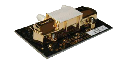
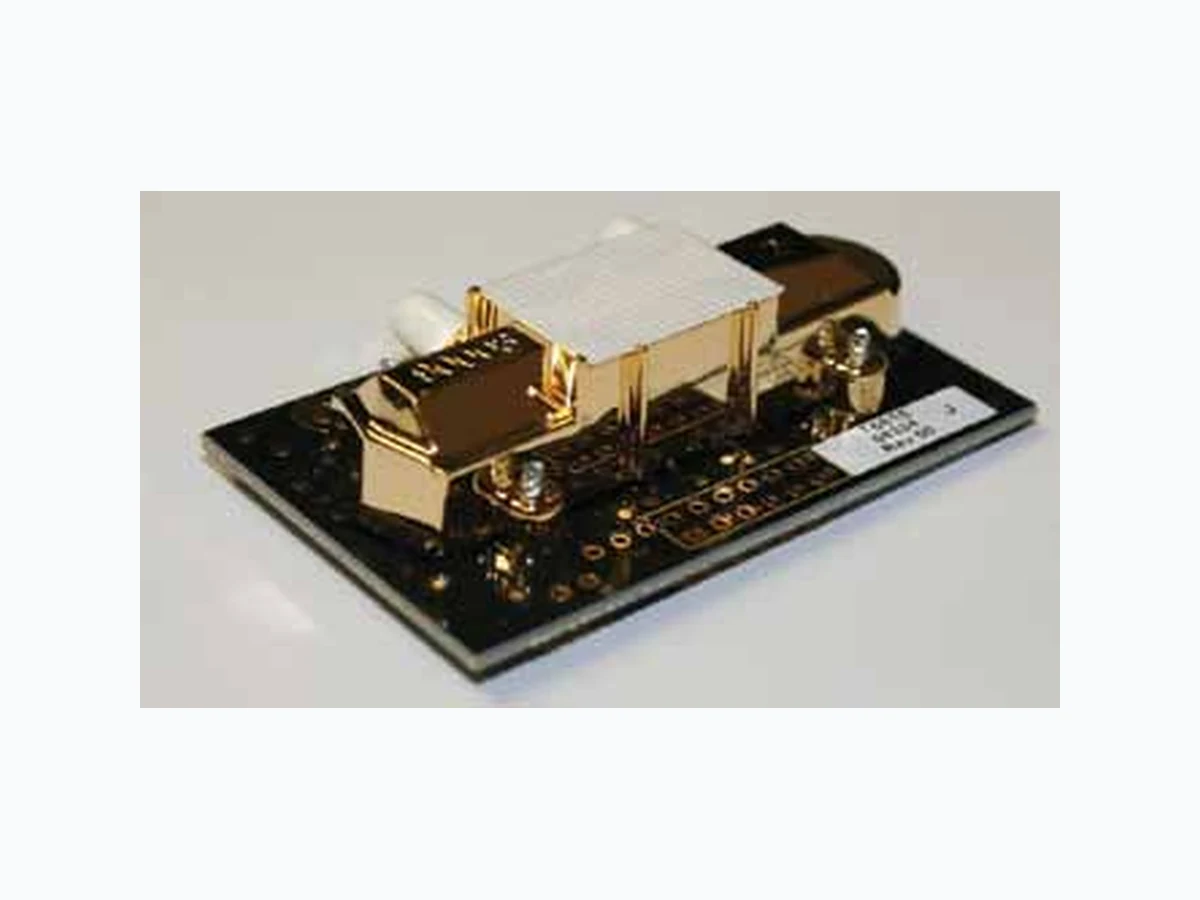
The Telaire® T6615 dual-channel CO2 Module is designed to meet the volume, cost, and delivery expectations of Original Equipment Manufacturers (OEMs).
Features
- An affordable gas sensing solution for OEMs.
- A reliable sensor design based on 15 years of engineering and manufacturing expertise.
- Flexible CO2 sensor platform designed to interact with other microprocessor devices.
- Dual-channel optical system and three-point calibration process for enhanced stability, accuracy and reliability.
- Designed for applications where ABC Logic cannot be used
- Sensor may be field calibrated
Page 2
Telaire T6615 Sensor Module Specifications
Method Dual-channel Non Dispersive Infrared (NDIR), gold plated optics, diffusion or flow through sampling.
Measurement Range 0 to 2000 ppm 0 to 5000 ppm 0 to 10,000 ppm 0 to 50,000 ppm
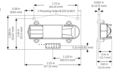
Dimensions 2.25 in X 1.365 in X 0.60 in (57.15 mm X 34.67 mm X 15.24 mm)
Accuracy\* 75 ppm or 10% of reading (whichever is greater)
Temperature Dependence 0.2% FS per °C
Stability over Life of Sensor (10 Years) < 5% of FS or <10% reading annual
Pressure Dependence 0.135% of reading per mm Hg
Response Time < 2 minutes for 90% step change typical
Warm Up Time
- < 2 minutes (operational)
- 10 minutes (maximum accuracy)
Operating Conditions
- 32°F to 122°F (0°C to 50°C)
- 0 to 95% RH, non condensing
Storage Conditions -40°F to 158°F (-40°C to 60°C)
(Non Condensating)
Output
Digital UART @ 19200 Baud (Please call for detailed product specifications). I2C slave up to 100 kHz
Analog 0 to 4 VDC
Power Supply Requirements 5 VDC regulated (±5%)
Power Consumption
- 0.90 watts peak
- 0.165 watts average
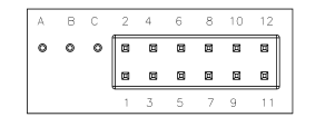
Interface Connections Designed for 12 pin male header with 0.1 in (2.54 mm) spacing. Header not included.
Flow Rates (Via Flow Ports) Flow through version: 50 cc/min maximum Diffusion version: 80 - 120 cc/min
Warranty Terms 12 months
\* Handling and OEM assembly may affect factory calibration.
Page 3
Sensor Accuracy and Field Calibration
The T6615 is a dual channel sensor. The two channels can be described as a CO2 channel that measures gas
concentration and a reference channel that measures the sensor signal intensity. The T6615 performs periodic self-calibrations using the reference channel. The self calibrations are approximately every 24 hours
but can also be initiated by sending a command (see communication protocol). Self calibrations should not be performed during the warm-up period. During the self
calibration the sensor PPM reading is frozen, it will not react to changing CO2. The calibration time is adjustable
but nominally two minutes.
Over time the minor electrical and mechanical changes can affect the sensor accuracy. With the exception of operation in harsh environments the rate of signal
change is a decaying function, thus the longer the sensor operates the more stable it will become. The reference channel will correct for these changes over time. GE
recommends periodic gas calibration depending on the application accuracy requirements. While the reference channel corrects for changes over time, a field calibration
using nitrogen gas will immediately restore the highest level of accuracy.
Pin Designations
Connector Pinout
Function
A
TX (UART)
B
RX (UART)
C
V+ (5 VDC)
1
V+ (5 VDC)
2
GND
3
GND
4
AV OUT (0 to 4 VDC)
I2C SCL
5
6
No Connect
I2C SDA
7
8
No Connect
9
No Connect
10
TX (UART)
11
RX (UART)
12
GND
Module T6615-F (Flow Through)
The diffusion membrane is replaced with a non- permeable seal. The two flow ports can be used for flow through sampling. Flow rate of 50 cc/min recommended.
Handling and Installation
The T6615 CO2 OEM modules are infrared gas sensors on
a printed circuit board and should be treated carefully. Precautions should be taken to observe specified limits and prevent damage from electrostatic discharge or
rough handling. Please refer to ANSI/ESD S20. 20-1999 for more information on preventing ESD damage and IPC 610 Rev D for more information on proper electronic assembly practices.
Available Models
Part Number
Sampling Method
Measurement Range
T6615
Diffusion
0-2,000 ppm
T6615-5K
Diffusion
0-5,000 ppm
T6615-10K
Diffusion
0-10,000 ppm
T6615-50K
Diffusion
0-50,000 ppm
T6615-F
Flow Through
0-2,000 ppm
T6615-5KF
Flow-through
0-5,000 ppm
T6615-10KF
Flow-through
0-10,000 ppm
T6615-50KF
Flow-through
0-50,000 ppm
T6615-R12
Diffusion, 12 second rate 0-2,000 ppm
Page 4
www.ge-mcs.com
920-474C
© 2011 General Electric Company. All Rights Reserved. Specifications are subject to change without notice. GE is a registered trademark of General Electric Company. Other company or product names mentioned in this document may be trademarks or registered trademarks of their respective companies, which are not affiliated with GE.