
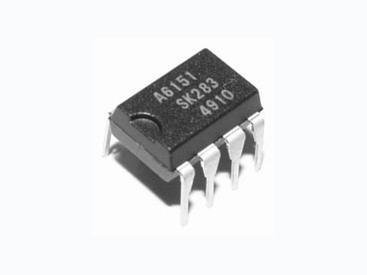
STR-A6131 ALLEGRO
Document overview
- Manufacturer or author: Provided By www.digicamel.com(FREE DATASHEET DOWNLOAD SITE)
- PDF pages: 7
Technical content
120 V/12 or 16 W
Flyback Switching Regulators Data Sheet 28103.21* STR-A6131 AND STR-A6132 Sanken Power Devices from Allegro MicroSystems Switching Regulators ABSOLUTE MAXIMUM RATINGS at TA = +25°C Control Supply Voltage, VCC . . . . 35 V Drain Switching Current, ID Peak Drain Switching Current, IDM Single-Pulse Avalanche Energy, EAS Start-Up-Pin Voltage Range, OCP Voltage Range, FB/OLP Voltage Range, Package Power Dissipation, PD MOSFET Channel Temp., TJ . +150°C Operating Temperature Range, Storage Temperature Range, * Drain switching current is limited by tem- perature (page 2) and safe operating area (page 4). †For the availability of parts meeting -40°C requirements, contact Allegro’s Sales Represen- tative. The STR-A6131 and STR-A6132 are PRC topology (fixed off-time) regulators specifically designed to satisfy the requirements for increased integration and reliability in flyback converters. They incorporate a primary control and drive circuit with avalanche-rated power MOSFETs. The STR-A6132 features higher switching current and avalanche-energy ratings and lower on-resistance. Covering the power range from below 12 watts to 16 watts for a 120 VAC input, these devices can be used in a range of applications, from DVD and VCR players to ac adapters for cellular phones and digital cameras. An auto-standby function reduces power consumption at light load, while multiple protections, including the avalanche energy guaran- teed MOSFET, provide high reliability of system design. Cycle-by-cycle current limiting, undervoltage lockout with hyster- esis, overvoltage protection, and thermal shutdown protect the power supply during the normal overload and fault conditions. Overvoltage protection and thermal shutdown are latched after a short delay. The latch may be reset by cycling the input supply. Low start-up current and a low-power standby mode selected from the secondary circuit completes a comprehensive suite of features. Both devices are provided in an 8-pin mini-DIP plastic package. FEATURES AND BENEFITS ■Rugged 500 V Avalanche-Rated MOSFET Simplified Surge Absorption No VDSS Derating Required ■Choice of rDS(on) (2.62 Ω or 3.95 Ω maximum) ■Two Operational Modes by Automatic Switching: PRC Mode for Normal Operation Burst Mode for Stand-By Operation or Light Loads ■Built-In Leading Edge Blanking ■Low Start-Up Current Start-Up Circuit Disabled in Operation ■Low Operating Current (1.5 mA typ) ■Automatic Burst Stand-By (intermittent operation) Input Power <0.1 W at No Load — continued Always order by complete part number, e.g., STR-A6131 .
Flyback Switching Regulators
115 Northeast Cutoff, Box 15036
Worcester, Massachusetts 01615-0036 Switching Regulators Copyright © 2005 Allegro MicroSystems, Inc. FUNCTIONAL BLOCK DIAGRAM FEATURES AND BENEFITS (cont’d) ■Auto-Bias Function Stable Burst Operation Without Generating Interference ■Internal Off-Timer Circuit ■Built-In Constant-Voltage Drive ■Multiple Protections: Pulse-by-Pulse Overcurrent Protection Overload Protection with Auto Recovery Latching Overvoltage Protection Undervoltage Lockout with Hysteresis Latching Thermal Shutdown ■Molded Small-Size 8-Pin Package For Low-Height SMPS Polarized to Prevent Backwards Assembly
Flyback Switching Regulators www.allegromicro.com Switching Regulators ELECTRICAL CHARACTERISTICS at TA = 25°C, VCC = 20 V (unless otherwise specified). Pin Ratings Characteristic No. Symbol Test Conditions Min Typ Max Units Drain-to-Source Breakdown Volt. 8 - 1 V(BR)DSS ID = 300 µA, 500 V V1 – V3 = 0 V (short) Drain Leakage Current 8 - 1 IDSS VDS = 500 V, 300 µA V1 – V3 = 0 V (short) On-State Resistance 8 - 1 rDS(on) STR-A6131, ID = 0.4 A 3.95 Ω STR-A6132, ID = 0.4 A 2.62 Ω MOSFET Switching Time 8 - 3 tf 250 ns Operation Start Voltage 2 - 3 VCC(ON) VCC = 0 19.2 V 17.5 19.2 V Operation Stop Voltage 2 - 3 VCC(OFF) VCC = 19.2 9 V 9.0 V Circuit Current in Operation 2 - 3 ICC(ON) 4.0 mA Circuit Current in Non-Operation 2 - 3 ICC(OFF) VCC = 14 V µA Auto-Bias Threshold Voltage 2 - 3 VCC(bias) VCC = 20 9.6 V 9.6 10.6 11.6 V VCC(bias) - VCC(OFF) 0.2 0.6 V Maximum OFF Time 8 - 3 tOFF 7.3 8.0 8.7 µs OCP Threshold Voltage 1 - 3 VOCP 0.69 0.77 0.86 V Leading Edge Blanking Time 8 - 3 tb 200 320 480 ns Burst Threshold Voltage 4 - 3 Vburst 0.70 0.79 0.88 V OLP Threshold Voltage 4 - 3 VOLP 6.5 7.2 7.9 V Current at OLP Operation 4 - 3 IOLP -18 -26 -35 µA Maximum FB Current 4 - 3 IFB(MAX) 227 300 388 µA Start-Up Current 5 - 3 Istartup VCC = 15 V 340 790 1230 µA Start-Up Circuit Leakage Current 5 - 3 Istart(leak) µA OVP Operation Voltage 2 - 3 VCC(OVP) VCC = 0 34.1 V 28.7 31.2 34.1 V OVP/TSD Latch Sustaining Current 2 - 3 ICC(H) VCC =34.1 8.5 V 200 µA OVP/TSD Latch Release Voltage 2 - 3 VCC VCC =34.1 6.6 V 6.6 7.3 8.0 V Thermal Shutdown TJ 135 Thermal Resistance RθJF °C/W WARNING — These devices are designed to be operated at lethal voltages and energy levels. Circuit designs that embody these components must conform with applicable safety requirements. Precautions must be taken to prevent accidental contact with power-line potentials. Do not connect grounded test equipment. The use of an isolation transformer is recommended during circuit development and breadboarding.
Flyback Switching Regulators Worcester, Massachusetts 01615-0036 Switching Regulators Avalanche energy is measured at VDD = 99 V, L = 20 mH, IL = 2.1 A. MOSFET TYPICAL CHARACTERISTICS STR-A6132 STR-A6131 Avalanche energy is measured at VDD = 99 V, L = 20 mH, IL = 2.6 A.
Flyback Switching Regulators www.allegromicro.com Switching Regulators MOSFET TYPICAL CHARACTERISTICS (cont’d) STR-A6131 STR-A6132
Flyback Switching Regulators Worcester, Massachusetts 01615-0036 Switching Regulators Complete product description and applications information is provided in Application Note 28103.20, Series STR- A6100 Flyback Switching Regulators. Typical Application APPLICATIONS INFORMATION The products described herein are manufactured in Japan by Sanken Electric Co., Ltd. for sale by Allegro MicroSystems, Inc. Sanken and Allegro reserve the right to make, from time to time, such departures from the detail specifications as may be required to permit improvements in the performance, reliability, or manufacturability of its products. Therefore, the user is cautioned to verify that the information in this publication is current before placing any order. When using the products described herein, the applicability and suitability of such products for the intended purpose shall be reviewed at the users responsibility. Although Sanken undertakes to enhance the quality and reliability of its products, the occurrence of failure and defect of semiconductor products at a certain rate is inevitable. Users of Sanken products are requested to take, at their own risk, preventative measures including safety design of the equipment or systems against any possible injury, death, fires or damages to society due to device failure or malfunction. Sanken products listed in this publication are designed and intended for use as components in general-purpose electronic equipment or apparatus (home appliances, office equipment, telecommunication equipment, measuring equipment, etc.). Their use in any application requiring radiation hardness assurance (e.g., aerospace equipment) is not supported. When considering the use of Sanken products in applications where higher reliability is required (transportation equipment and its control systems or equipment, fire- or burglar-alarm systems, various safety devices, etc.), contact a company sales representative to discuss and obtain written confirmation of your specifications. The use of Sanken products without the written consent of Sanken in applications where extremely high reliability is required (aerospace equipment, nuclear power-control stations, life-support systems, etc.) is strictly prohibited. The information included herein is believed to be accurate and reliable. Application and operation examples described in this publica- tion are given for reference only and Sanken and Allegro assume no responsibility for any infringement of industrial property rights, intellectual property rights, or any other rights of Sanken or Allegro or any third party that may result from its use.
Flyback Switching Regulators www.allegromicro.com Switching Regulators PACKAGE DIMENSIONS Dimensions in Millimeters (controlling dimensions) Product Weight: Approx. 0.51 g. Frame temperature, TF, is measured at the root of pin 3. Dimensions in Inches (for reference only) EI16EI