
STM-16 ETC2
Document overview
- Manufacturer or author: Provided By www.digicamel.com(FREE DATASHEET DOWNLOAD SITE)
- PDF pages: 6
Technical content
mesytec GmbH & Co. KG Wernher-von-Braun- Str. 1, D-85640 Putzbrunn, Germany fon: +49 - 89 / 456007-30 fax: +49 - 89 / 456007-50 info@mesytec.com - www.mesytec.com STM-16+ V2.3 16 fold Spectroscopy Amplifier with Discriminators and Multiplicity Trigger mesytec STM-16 is a shaping / timing filter am plifier with discriminator and multiplicity trigger. It is well suited for multistrip silic on detectors and for high quality spectroscopy applications. The differential input version is ideal with the preamplifier family MPR-16 / -32 / -64. Features STM-16:
- 16 channel NIM module, low power design
- Shaper amplifiers with baseline restorer
- Timing filter amplifiers
- Leading edge discriminators
- Digital delay of 450 ns for timing stop
- ECL timing output
- Trigger output
- Multiplicity trigger
- Option: Remote control of discriminator thresholds and gains New Features for STM-16+:
- 2 shaping times: 0.4µs / 1µs or 2µs / 5µs (= 1us/ 2us or 5us / 12us FWHM)
- Gain adjustable from 1 to 600
- Unipolar Lemo input option.
- Low noise: < 7µV (gain=100 and shaping time = 2µs)
- Low integral nonlinearity Schematics: Differential Unipolar Version
mesytec STM-16+ 16 fold shaper with timing mesytec GmbH & Co. KG wernher-von-braun- str. 1, 85640 putzbrunn, germany fon: +49 - 89 / 456007-30, fax : +49 - 89 / 456007-50 info@mesytec.com - www.mesytec.com Technical Data: Input stage
- Gain adjust: gain can be set from 1 to 20 in 16 steps with factor 1.22 per step. differential version
- Input connector: 34 pin male connector
- Input resistance: terminated with 100 Ω, adapted to twisted pair cables.
- Gain-Polarity jumper with multiplication factor of 2 and 30 are standard. (Gain range from 2 to 600)
- input noise at gain = 100: 10 µVrms for 1us shaping time, 7 µVrms for 2 µs shaping time.
- Common mode suppression: 50 dB unipolar version
- 16 Lemo 00 input connectors
- Input termination option: 1k and 50 Ohm, coded on the gain-polarity jumper.
- Gain-Polarity jumper with multiplica- tion factor 2 and 30 are standard. Op- tion: multiplication factor 1.
- input noise at gain = 100 and 2 µs shaping time = 7 µVrms. Shaper:
- PZ adjustable with trimmers inside the case from 8 µs to infinity.
- Two shaping times of 0.4 µs / 1 µs or 2 µs / 5 µs jumper selectable, common for all channels.
- Output amplitude: 0 to 10 V
- Passive baseline restorer
- DC-Offset: VDC ± 5 mV, common offset adjust.
- Output connector: 34 pin male connector
- Integral nonlinearity < 0.05%
- gain drift < 0.0075% / °C
- Offset drift < 50 µV/ °C Timing filter amplifier:
- RC-CR, 7 ns / 100 ns
- 4 monitor outputs for timing filter signals, each providing the sum signal of 4 channels (Amplitude: -1.5 V per channel for 10 V shaper output) Discriminator:
- Leading edge
- Threshold: adjustable, 0 to 4 V (= 0% to 40% of maximum range) Gate generator, Timing delay, ECL output
- Pulse width for trigger output: 400 ns
- Timing stop- ECL-Signals: delay 400 ns from trigger, width 200 ns
- Output connector: 34 pin male connector
- Typical timing resolution for 5 MeV signals from silicon detector (10 * 10 mm 2, 500 µm, 60V bias): dT = 400 ps. If necessary, a walk correction can be easily implemented in software using the shaper amplitude. Multiplicity trigger:
- Each channel above threshold contributes to multiplicity level, a multiplicity trigger is generated for: lower multiplicity threshold ≤ multiplicity level ≤ upper multiplicity threshold
- coincidence interval adjustable from 40 ns up to 150 ns (default 100 ns).
- The multiplicity trigger is 100 ns delayed to the trigger signal.
- Lower multiplicity threshold: 1 … 8, upper multiplicity threshold: 1 … 8 and ∞
- Multiplicity chaining: multiplicity outputs from several modules can be connected, re- sulting in a total multiplicity level of all connected modules. Multiplicity trigger windows of the connected modules act in- dependently on the total multiplicity. Power consumption: (max 7W)
- +6V 280 mA
- -6V –680 mA
- +12V 80 mA Remote control The modules are prepared for the remote con- trol of 1) individual thresholds 2) gains for pairs of channels. The remote control unit is a plug in module which can also be inserted as an upgrade.
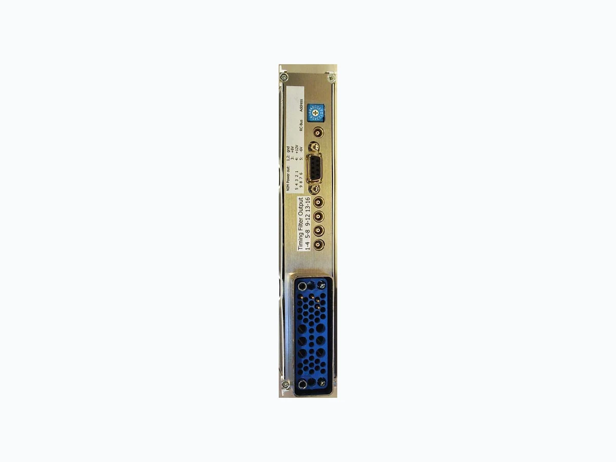
mesytec STM-16+ 16 fold shaper with timing mesytec GmbH & Co. KG wernher-von-braun- str. 1, 85640 putzbrunn, germany fon: +49 - 89 / 456007-30, fax : +49 - 89 / 456007-50 info@mesytec.com - www.mesytec.com Remote Control The STM-16 can be equipped with a remote con- trol option which is separately available . The NIM-controller module MRC-1 is necessary as a bus master. One MRC-1 can control 32 vari- ous mesytec modules. Communication with a control PC is done via RS-232 serial interface. The discriminator thresholds can be individually adjusted from 0..40% of the maximum range in 256 steps. The gain can be adjusted for pairs of channels in 16 steps: setting 0 = gain 1, setting 15 = gain20, The parameters are organised in a 32 word mem- ory array. The gain parameters are situated at the 15/16) , the thresholds are situated at the odd posi- The commands are transmitted via event bus, which can be connected to the rear side of the STM-16 module. The ID-number which is set with the coder identifies the module in the bus chain and must be unique for one bus line. Rear side of STM-16: Coder for 16 bus addresses (0..F) Bidirectional event bus Power supply output for preamp MPR- Timing filter sum outputs in groups of 4 channels (1-4, 5-8, 9-12, 13-16)
mesytec STM-16+ 16 fold shaper with timing mesytec GmbH & Co. KG wernher-von-braun- str. 1, 85640 putzbrunn, germany fon: +49 - 89 / 456007-30, fax : +49 - 89 / 456007-50 info@mesytec.com - www.mesytec.com View on the PCB with servicable trimmers
mesytec STM-16+ 16 fold shaper with timing mesytec GmbH & Co. KG wernher-von-braun- str. 1, 85640 putzbrunn, germany fon: +49 - 89 / 456007-30, fax : +49 - 89 / 456007-50 info@mesytec.com - www.mesytec.com Memory List STM-16+: ADR GAIN/THR ADR GAIN/THR 0 gain 1 and 2 16 gain 9 and 10 1 threshold 1 17 threshold 9 3 threshold 2 19 threshold 10 4 gain 3 and 4 20 gain 11 and 12 5 threshold 3 21 threshold 11 7 threshold 4 23 threshold 12 8 gain 5 and 6 24 gain 13 and 14 9 threshold 5 25 threshold 13 11 threshold 6 27 threshold 14 12 gain 7 and 8 28 gain 15 and 16 13 threshold 7 29 threshold 15 15 threshold 8 31 threshold 16 The memory positions can be written with SE command and can be read with RE command. A mirror page is available. It can be written with SM and read with RM and copied with CP. The commands RST sets all thresholds to the value 32 and all gains to the value gain = 2. The ON/OFF command makes the remote control active or inactive. The power up default is inactive. While inactive the manual values from the front panel elements are set. Identification code for STM (detected when running the scan bus command "SC") is IDC = 19 Example: reset all channels of STM-16 module ID 7 on bus 0 to defined values: RST 0 7 to set the channel 3 and 4 of module with ID 7 on bus 0 to gain = 1.5 and the threshold of channel 3 20% type: SE 0 7 4 2 //set gain of channel 3 and 4 = address 4 SE 0 7 5 128 // set threshold of channel 3 = address 5 activate remote control ON 0 7
mesytec STM-16+ 16 fold shaper with timing mesytec GmbH & Co. KG wernher-von-braun- str. 1, 85640 putzbrunn, germany fon: +49 - 89 / 456007-30, fax : +49 - 89 / 456007-50 info@mesytec.com - www.mesytec.com Command Summary: data formats: bus = bus number [0...1] dev = device number [0…15] adr = parameter number [0…31] gain = [0…15]; gain from 1 to 20 in steps of factor 1.22; thr = [0…255]; 0..255 corresponds to threshold 0..40% maxrange M n e m o n i c D e s c r i p t i o n SC bus STM 16 allows scan bu s, returns id code: IDC=19 ON bus dev activate RC OFF bus dev deactivate RC SE bus dev adr gain/thr set gain(even address) or threshold (odd address) RE bus dev adr read gain or threshold value RST bus dev reset gain and thre shold to default values SM bus dev adr gain/thr set mirror parameter (even address = gain, odd address = threshold) RM bus dev adr read mirror cell CP copy mirror to active memory