
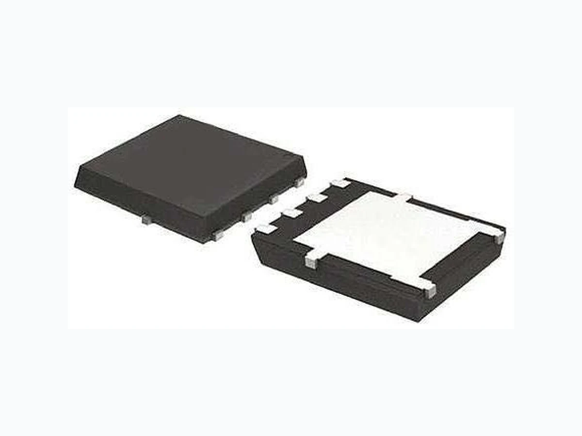
STL12P6F6 LEIDITECH
Document overview
- Manufacturer or author: Provided By www.digicamel.com(FREE DATASHEET DOWNLOAD SITE)
- PDF pages: 5
Technical content
Description
The uses advanced trench technology to provide excellent RDS(ON), low gate charge and operation with gate voltages as low as 4.5V. This device is suitable for use as a Battery protection or in other Switching application. General Features VDS = -100V ID =-50A RDS(ON) < 52mΩ @ VGS=10V (Type:40mΩ) Application Brushless motor Load switch Uninterruptible power supply Package Marking and Ordering Information Product ID Pack Marking Qty(PCS) DFN5*6-8L AP50P10NF XXX YYYY 5000 Absolute Maximum Ratings (TC=25℃unless otherwise noted) Symbol Parameter Rating Units VDS Drain-Source Voltage -100 V VGS Gate-Source Voltage ±20 V ID@TC=25℃ Continuous Drain Current, VGS @ -10V1 -50 A ID@TC=100℃ Continuous Drain Current, VGS @ -10V1 -28 A IDM Pulsed Drain Current2 -150 A EAS Single Pulse Avalanche Energy3 87 mJ IAS Avalanche Current -35 A PD@TC=25℃ Total Power Dissipation4 140 W TSTG Storage Temperature Range -55 to 150 ℃ TJ Operating Junction Temperature Range -55 to 150 ℃ RθJA Thermal Resistance Junction-Ambient 1 25 ℃/W RθJC Thermal Resistance Junction-Case1 1.1 ℃/W -100V P-Channel Enhancement Mode MOSFET www.leiditech.comRev : 1 / 501.09.2021 STL12P6F6 STL12P6F6 STL12P6F6
P-Channel Electrical Characteristics (TJ =25 ℃, unless otherwise noted) Symbol Parameter Test Condition Min. Typ. Max. Units V(BR)DSS Drain-Source Breakdown Voltage VGS=0V, ID=-250μA -100 - - V IDSS Zero Gate Voltage Drain Current VDS=-100V, VGS=0V, - - -1.0 μA IGSS Gate to Body Leakage Current VDS=0V, VGS= ±20V - - ±100 nA VGS(th) Gate Threshold Voltage VDS=VGS, ID=-250μA -1.0 -1.6 -2.5 V RDS(on) Static Drain-Source on-Resistance VGS=-10V, ID=-20A - 40 52 mΩ VGS=-4.5V, ID=-10A - 44 62 Ciss Input Capacitance VDS=-50V, VGS=0V, f=1.0MHz - 2120 - pF Coss Output Capacitance - 194 - pF Crss Reverse Transfer Capacitance - 13 - pF Qg Total Gate Charge VDS=-50V, ID=-5A, VGS=-10V - 40 - nC Qgs Gate-Source Charge - 7.8 - nC Qgd Gate-Drain(“Miller”) Charge - 8.6 - nC td(on) Turn-on Delay Time VDD=-50V, ID=-5A, RG=6Ω, VGS=-10V - 13 - ns tr Turn-on Rise Time - 39 - ns td(off) Turn-off Delay Time - 100.1 - ns tf Turn-off Fall Time - 105.3 - ns IS Maximum Continuous Drain to Source Diode Forward Current - - -35 A ISM Maximum Pulsed Drain to Source Diode Forward Current - - -140 A VSD Drain to Source Diode Forward Voltage VGS=0V, IS=-30A - - -1.2 V trr Body Diode Reverse Recovery Time TJ=25℃, IF=-5A,dI/dt=100A/μs - 104 - ns Qrr Body Diode Reverse Recovery Charge - 280 - nC Note : 1、The data tested by surface mounted on a 1 inch 2 FR-4 board with 2OZ copper. 2、The data tested by pulsed , pulse width ≦ 300us , duty cycle ≦ 2% 3、The EAS data shows Max. rating . The test condition is V DD =-25V,V GS =-10V,L=0.1mH,IAS =-24A 4、The power dissipation is limited by 150℃ junction temperature 5、The data is theoretically the same as I D and I DM , in real applications , should be limited by total power dissipation. www.leiditech.comRev : 2 / 501.09.2021 STL12P6F6
A 1.03 1.17 0.0406 0.0461 b 0.34 0.48 0.0134 0.0189 c 0.824 0.0970 0.0324 0.082 D 4.80 5.40 0.1890 0.2126 D1 4.11 4.31 0.1618 0.1697 D2 4.80 5.00 0.1890 0.1969 E 5.95 6.15 0.2343 0.2421 E1 5.65 5.85 0.2224 0.2303 E2 1.60 / 0.0630 / e 1.27 BSC 0.05 BSC L 0.05 0.25 0.0020 0.0098 L1 0.38 0.50 0.0150 0.0197 L2 0.38 0.50 0.0150 0.0197 H 3.30 3.50 0.1299 0.1378 I / 0.18 / 0.0070 www.leiditech.comRev : Shanghai Leiditech Electronic Co.,Ltd Email: sale1@leiditech.com Tel : +86- 021 50828806 Fax : +86- 021 50477059 01.09.2021 STL12P6F6