
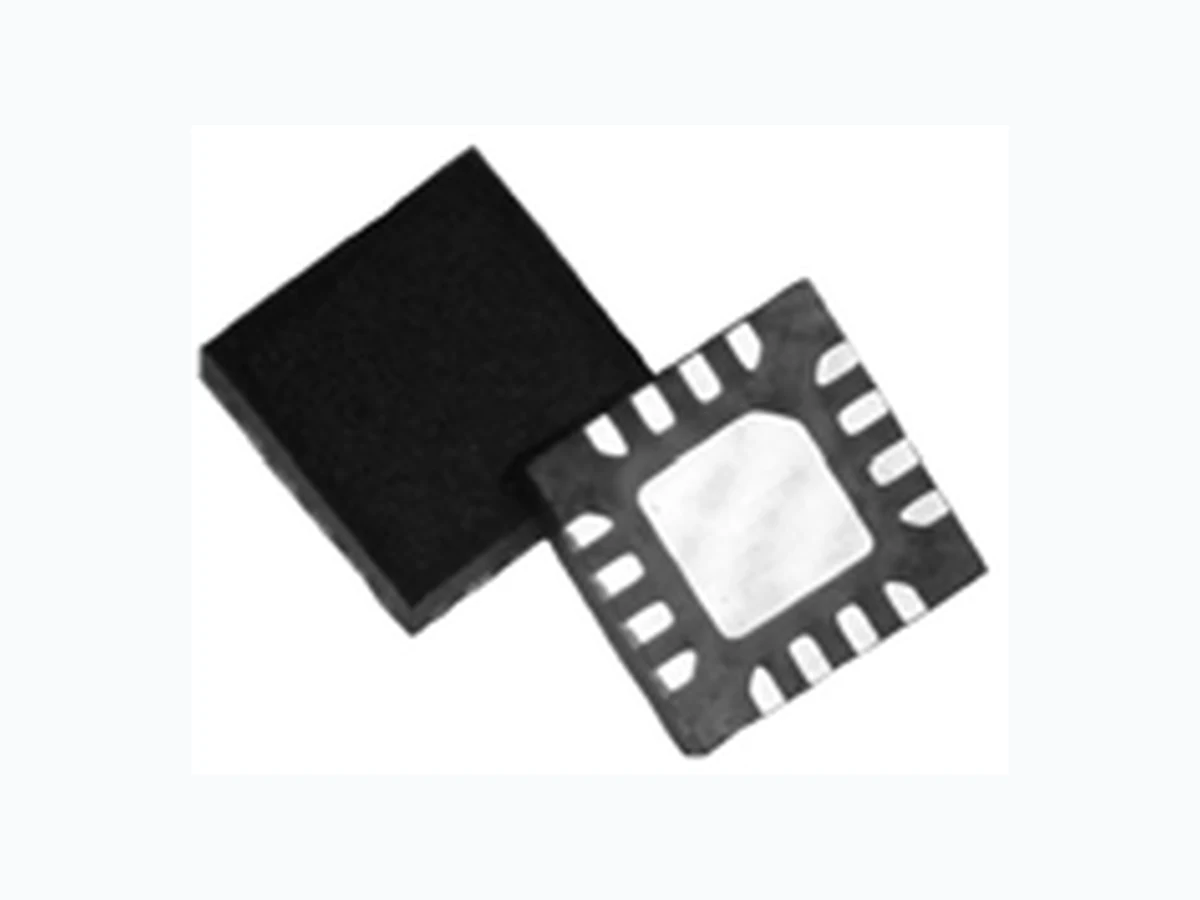
STA-6033 ETC
Document overview
- Manufacturer or author: Provided By www.digicamel.com(FREE DATASHEET DOWNLOAD SITE)
- PDF pages: 8
Technical content
The information provided herein is believed to be reliable at press time. Sirenza Microdevices assumes no responsibility for inaccuracies or ommisions. Sirenza Microdevices assumes no responsibility for the use of this information, and all such information shall be entirely at the user’s own risk. Prices and specifications are subject to change without notice. No patent rights or licenses to any of the circuits described herein are implied or granted to any third party. Sirenza Microdevices does not authorize or warrant any Sirenza Microdevices product for use in life-support devices and/or systems. Copyright 2002 Sirenza Microdevices, Inc. All worldwide rights reserved. 303 South Technology Court Broomfield, CO 80021 Phone: (800) SMI-MMIC http://www.sirenza.com
1 EDS-103643 Rev B
Sirenza Microdevices’ STA-6033 is a high efficiency class AB Heterojunction Bipolar Transistor (HBT) amplifier housed in a low-cost surface-mountable plastic package. This HBT amplifier is made with InGaP on GaAs device technology and fabricated with MOCVD for an ideal com- bination of low cost and high reliability. This product is specifically designed as a final stage for 802.11a equipment in the 4.9 - 5.9 GHz band. It can run from a 3.0V to 3.6V supply. Optimized on-chip impedance matching circuitry provides a 50Ω nominal RF input imped- ance. A single external output matching circuit covers the entire 4.9-5.9GHz band. The external output match allows for load line optimization for other applications or opti- mized performance over narrower bands. It is designed as a drop in replacement for similar parts in its class.Key Specifications Symbol Parameters: Test Conditions, App circuit page 4 Z0 = 50Ω, VCC = Vpc = 3.3V, Icq = 165mA, TBP = 30ºC Unit Min. Typ. Max. fO Frequency of Operation MHz 4900 5900 P1dB Output Power at 1dB Compression – 4.9 GHz dBm 26.5 Output Power at 1dB Compression – 5.875 GHz 24.0 25.5 S21 Gain at 4.9 GHz dB 28.0 30.0 32.0 Gain at 5.875 GHz 23.6 25.6 27.6 Pout Output power at 3% EVM 802.11a 54Mb/s - 5.15GHz dBm Output Power at 3% EVM 802.11a 54Mb/s - 5.875GHz 18 IM3 Third Order Intermod at Pout=15dBm per tone - 5.875GHz dBc -38 -34 NF Noise Figure at 5.875 GHz dB 5.7 IRL Worst Case Input Return Loss 4.9-5.875GHz dB 11 15 ORL Worst Case Output Return Loss 4.9-5.875GHz 8 12 Vdet Range Output Voltage Range for Pout=7dBm to 23dBm V 0.8 to 1.5 Icq Vcc Quiescent Current mA 140 165 190 IVPC Power Up Control Current,Vpc=3.3V ( IVPC1 + IVPC2 + IVPC3)m A 1 . 5 Rth, j-l Thermal Resistance (junction - lead) ºC/W 28 Functional Block Diagram STA-6033 4.9 – 5.9 GHz 3.3V Power Amplifier Product Features
Applications
- 802.11a 54Mb/s Class AB Performance Pout = 18dBm @ 3% EVM, 3.3V, 210mA
- High Gain = 27dB
- Output Return Loss < -12dB for Linear Tune
- On-chip Output Power Detector
- Simultaneous 4.9- 5.9GHz Broadband
- Pin Compatible with Microsemi LX5506
- Robust - Survives RF Input Power = +20dBm
- Power up/down control < 1µs
- 802.11a WLAN, OFDM
- General purpose 5.8GHz ISM Band
- 802.16 WiMax, Fixed Wireless, UNII Product Description RFIN RFOUT Vcc Power Detector Vout Activ e Bias Activ e Bias Activ e Bias Pow er Up/Dow n Control 16 pin 3mm x 3mm QFN
303 South Technology Court Broomfield, CO 80021 Phone: (800) SMI-MMIC http://www.sirenza.com
2 EDS-103643 Rev B
STA-6033 4.9-5.9 GHz Power Amp Pin Out Description Pin # Function Description 1,4,9,12,13 N/C Pins are not used. May be grounded, left open, or connected to adjacent pin. 5V P C 1 VPC1 is the bias control pin for the stage 1 active bias circuit. An external series resistor is required for proper setting of bias levels. Refer to the evaluation board schematic for resistor value. To prevent potential damage, do not apply voltage to this pin that is +1V greater than voltage applied to pin 16 (Vbias) unless Vpc supply current capability is less than 10 mA. 6V P C 2 VPC2 is the bias control pin for the stage 2 active bias circuit. An external series resistor is required for proper setting of bias levels. Refer to the evaluation board schematic for resistor value. To prevent potential damage, do not apply voltage to this pin that is +1V greater than voltage applied to pin 16 (Vbias) unless Vpc supply current capability is less than 10 mA. 7V P C 3 VPC3 is the control pin for the stage 3 active bias circuits. An external series resistor is required for proper set- ting of bias levels. Refer to the evaluation board schematic for resistor value. To prevent potential damage, do not apply voltage to this pin that is +1V greater than voltage applied to pin 16 (Vbias) unless Vpc supply current capability is less than 10 mA. 8 Vdet Ouput power detector voltage. Load with 10K-100K ohms to ground for best performance. 2,3 RFIN RF input pins. This is DC grounded internal to the IC. Do not apply voltage to this pin. All three pins must be used for proper operation. 10,11 RFOUT RF output pin. This is also another connection to the 3rd stage collector 14 VC3 3rd stage collector bias pin. Apply 3.0V to 3.6V to this pin. 15 VC2 2nd stage collector bias pin. Apply 3.0V to 3.6V to this pin. 16 VC1,Vbias 1st stage collector bias pin and active bias network VCC. Apply 3.0V to 3.6V to this pin. EPAD Gnd Exposed area on the bottom side of the package needs to be soldered to the ground plane of the board for optimum thermal and RF performance. Several vias should be located under the EPAD as shown in the rec- ommended land pattern (page 5). Caution: ESD Sensitive Appropriate precaution in handling, packaging and testing devices must be observed. Absolute Maximum Ratings Parameters Value Unit VC3 Collector Bias Current (pin16) 400 mA VC2 Collector Bias Current (pin18) 140 mA VC1 Collector Bias Current (pin19) 50 mA Device Voltage (V D)4 . 5 V Power Dissipation 1.4 W Operating Lead Temperature (T L) -40 to +85 ºC RF Input Power for 50 ohm load 20 dBm Storage Temperature Range -40 to +150 ºC Operating Junction Temperature (T J)+ 1 5 0 º C ESD Human Body Model >1000 V Operation of this device beyond any one of these limits may cause permanent damage. For reliable continuous operation the device voltage and current must not exceed the maximum operating values specified in the table on page one. Bias conditions should also satisfy the following expression: IDVD < (TJ - TL) / RTH’ j-l Simplified Device Schematic Stage 1 Bias Stage 2 Bias Stage 3 Bias Pin 2, 3 Pin 10,11 Pin Pin Pin Pin Pin Pin Pin EPAD EPAD EPAD
303 South Technology Court Broomfield, CO 80021 Phone: (800) SMI-MMIC http://www.sirenza.com
3 EDS-103643 Rev B
STA-6033 4.9-5.9 GHz Power Amp 4.9 - 5.9 GHz Evaluation Board Data (Vcc = Vpc = 3.3V, Iq = 165mA) Typical S11 Input Return Loss -30 -25 -20 -15 -10 4 . 555 . 566 . 5 Frequency(GHz) S11(dB) +25c 0c -40c +70c +85c Typical S21 Gain 4 . 555 . 566 . 5 Frequency(GHz) S21(dB) +25c 0c -40c +70c +85c Gain vs Pout, T=25c 10 12 14 16 18 20 22 24 26 28 Pout (dBm) Gain(dB) Typical S22 Input Return Loss -25 -20 -15 -10 4.5 5 5.5 6 6.5 Frequency(GHz) S22(dB) +25c 0c -40c +70c +85c IM3 vs Pout (per tone) T=+25c Tone spacing = 1.2MHz -70 -60 -50 -40 -30 -20 0 5 10 15 20 25 Pout(dBm) IM3(dBc) Intentionally left blank
303 South Technology Court Broomfield, CO 80021 Phone: (800) SMI-MMIC http://www.sirenza.com
4 EDS-103643 Rev B
STA-6033 4.9-5.9 GHz Power Amp Icq vs Vcc (Vcc and Vpc tied together) 0.05 0.1 0.15 0.2 0.25 0.3 0.35 0.4 0.45 Vcc/Vpc(V) Icq(A) +25c 0c -40c +70c +85c Idc vs Pout, T=25c 0.15 0.2 0.25 0.3 0.35 0.4 0.45 10 12 14 16 18 20 22 24 26 Pout(dBm) Idc(A) Icq vs Vpc vs Vpc Enable Set Voltage, For Fixed Vcc=3.3v , T=+25c 0.05 0.1 0.15 0.2 0.25 0.3 Swept VPC (V) Icq(A) 4.9 - 5.9 GHz Evaluation Board Data (Vcc = 3.3V, Iq = 165mA) POUT @ 3% EVM vs Vcc for Fixed Vpc=3.3, F=5.725GHz 15.5 16.5 17.5 18.5 19.5 Vcc(V) Pout(dBm) 0c +25c +70c EVM(%) @ Pout=18dBm vs. Vpc Set Voltage vs. Temp F=5.725GHz 1.5 2.5 3.5 - 4 0 - 2 0 0 2 04 06 08 0 1 0 0 Temp(C) EVM(%) 2.9v 3v 3.1v 3.2v 3.3v Intentionally left blank
303 South Technology Court Broomfield, CO 80021 Phone: (800) SMI-MMIC http://www.sirenza.com
5 EDS-103643 Rev B
STA-6033 4.9-5.9 GHz Power Amp 4.9 - 5.9 GHz Evaluation Board Data (Vcc = Vpc = 3.3V, Iq = 165mA) 802.11a EVM, OFDM, 54Mb/s, 64QAM EVM vs Pout, F=4.9GHz 0.5 1.5 2.5 3.5 4.5 4 6 8 1 01 21 41 61 82 0 POUT(dBm) EVM(%) +25c 0c -40c +70c +85c EVM vs Pout, T=25c 4 6 8 1 01 21 41 61 82 0 Pout(dBm) EVM(%) EVM vs Pout, F=5.15GHz 0.5 1.5 2.5 3.5 4.5 4 6 8 1 01 21 41 61 82 0 POUT(dBm) EVM(%) +25c 0c -40c +70c +85c EVM vs Pout, F=5.35GHz 0.5 1.5 2.5 3.5 4.5 4 6 8 1 01 21 41 61 82 0 POUT(dBm) EVM(%) +25c 0c -40c +70c +85c EVM vs Pout, F=5.725GHz 4 6 8 10 12 14 16 18 20 POUT(dBm) EVM(%) +25c 0c -40c +70c +85c EVM vs Pout, F=5.875GHz 4 6 8 1 01 21 41 61 82 0 POUT(dBm) EVM(%) +25c 0c -40c +70c +85c
303 South Technology Court Broomfield, CO 80021 Phone: (800) SMI-MMIC http://www.sirenza.com
6 EDS-103643 Rev B
STA-6033 4.9-5.9 GHz Power Amp 4.9 - 5.9 GHz Evaluation Board Data (Vcc = Vpc= 3.3V, Iq = 165mA) RF detector output (Vdet) vs Pout, T=25c 0.70 0.90 1.10 1.30 1.50 1.70 1.90 2.10 2.30 Output Power(dBm) Vdet(V) RF detector output(Vdet) vs Pout, F=4.9G Hz 0.8 1.2 1.4 1.6 1.8 10 12 14 16 18 20 22 24 26 Pout(dBm) Vdet(V) +25c 0c -40c +70c +85c RF detector output(Vdet) vs Pout, F=5.15GHz 0.8 1.2 1.4 1.6 1.8 10 12 14 16 18 20 22 24 26 Pout(dBm) Vdet(V) +25c 0c -40c +70c +85c RF detector output(Vdet) vs Pout, F=5.35GHz 0.8 1.2 1.4 1.6 1.8 10 12 14 16 18 20 22 24 26 Pout(dBm) Vdet(V) +25c 0c -40c +70c +85c RF detector output(Vdet) vs Pout, F=5.725GHz 0.8 1.2 1.4 1.6 1.8 10 12 14 16 18 20 22 24 26 Pout(dBm) Vdet(V) +25c 0c -40c +70c +85c RF detector output(Vdet) vs Pout F=5.875GHz 0.8 1.2 1.4 1.6 1.8 10 12 14 16 18 20 22 24 26 Pout(dBm) Vdet(V) +25c 0c -40c +70c +85c
303 South Technology Court Broomfield, CO 80021 Phone: (800) SMI-MMIC http://www.sirenza.com
7 EDS-103643 Rev B
STA-6033 4.9-5.9 GHz Power Amp 4.9 - 5.9 GHz Evaluation Board Schematic For Vcc = Vpc = V+ = 3.3V Supply R3 R4 4.9 - 5.9 GHz Evaluation Board Layout For Vcc = Vpc = V+ = 3.3V Supply - Board material GETEK, 10mil thick, Dk=3.9, 2 oz. copper finish Notes: Pins 1,4,9,12,13 are unwired (N/C) inside the package. Refer to page 2 for detailed pin descriptions. Some of these pins are wired to adjacent pins or grounded as shown in the application circuit. This is to main- tain consistency with the evaluation board layout shown below. It is rec- ommended to use this layout and wiring to achieve the specified per- formance. To prevent potential damage, do not apply voltage to the Vpc pin that is +1V greater than voltage applied to pin 16 (Vbias/Vcc) unless Vpc sup- ply current capability is less than 10 mA. See table below for other Vpc logic level resistor values. See AN-064 if using other than Vcc=3.3V for Vpc resistors values.
303 South Technology Court Broomfield, CO 80021 Phone: (800) SMI-MMIC http://www.sirenza.com
8 EDS-103643 Rev B
STA-6033 4.9-5.9 GHz Power Amp Package Outline Drawing (dimensions in mm ): Part Number Ordering Information Part Number Reel Size Devices/Reel STA-6033 13” 3000 Part Symbolization The part will be symbolized with an “STA-6033” mark- ing designator on the top surface of the package. 0.015 0.011 0.062 0.062 0.030 0.010 0.020 DIMENSIONS IN INCHES Ø0.015 PLATED THRU (4PL)
0.005 CHAMFER
(8PL) 0.008 Recommended Land Pattern (dimensions in inches): Caution: ESD Sensitive Appropriate precaution in handling, packaging and testing devices must be observed.