
STA VISHAY
Document overview
- Manufacturer or author: Provided By www.digicamel.com(FREE DATASHEET DOWNLOAD SITE)
- PDF pages: 3
Technical content
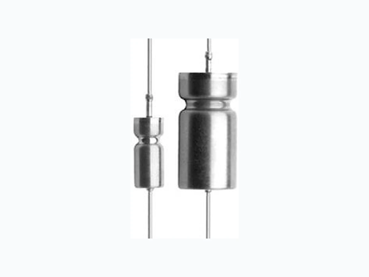
www.vishay.com Vishay Revision: 13-Oct-2020 1 Document Number: 43013 For technical questions, contact: tantalum@vishay.com THIS DOCUMENT IS SUBJECT TO CHANGE WITHOUT NOTICE. THE PRODUCTS DESCRIBED HEREIN AND THIS DOCUMENT ARE SUBJECT TO SPECIFIC DISCLAIMERS, SET FORTH AT www.vishay.com/doc?91000 Wet Tantalum Capacitors with Hermetic Seal Vishay STA represents a ma jor breakthrough in Wet Tantalum capacitor technology. Its unique cathode system, also used in the ST, provides the highest capacitance per unit volume available. The STA combines the inherent reliability of wet tantalum with the capacitance stability of solid tantalum, and there are no circuit impedance restrictions. The range is exceptionally well suited for low voltage filtering and energy storage applications.
FEATURES
- All tantalum, hermetically sealed case
- Terminations: axial leaded
- Utilizes proven Vishay SuperTan ® technology
- High and stable capacitance
- High reliability, rugged design
- 150 μF to 4700 μF
- 6 V DC to 15 VDC APPLICATIONS NOTES a) No continuous reverse voltage permissible. b) Transient reverse voltage surges are acceptable under the following conditions: The peak reverse voltage does not exceed 1.5 V and the peak current times the durati on of the reverse transient does not exceed 0.05 As. In addition, the repetition frequency of the reverse voltage surge is less than 10 Hz. c) The peak of the applied AC ripple and the applied DC voltage must not exceed the DC voltage rating of the capacitor. d) Ripple current ratings by part number at 85 °C and 40 kHz are included in the table. Ripple current correction factors for other temperatures and frequencies are given on the next page. Notes
- Material at egress is tantalum.
- Insulation sleeving will lap over the ends of the capacitor case.
- Tinned nickel leads, solderable and weldable.
- Approx. weight T3: 9.4 g, T4: 14.8 g
ORDERING INFORMATION
STYLE CAPACITANCE 85 °C RATED CASE CODE CAPACITANCE INSULATING μF DC VOLTAGE TOLERANCE SLEEVE M = ± 20 % K = ± 10 % I = insulated X = uninsulated DIMENSIONS in inches [millimeters] 0.025 + 0.002 MAX. ELE 0.094 (2.38) MAX. Terminal welded to case Terminal location within 0.031 of center “D” Dia.
www.vishay.com Vishay Revision: 13-Oct-2020 2 Document Number: 43013 For technical questions, contact: tantalum@vishay.com THIS DOCUMENT IS SUBJECT TO CHANGE WITHOUT NOTICE. THE PRODUCTS DESCRIBED HEREIN AND THIS DOCUMENT ARE SUBJECT TO SPECIFIC DISCLAIMERS, SET FORTH AT www.vishay.com/doc?91000 STANDARD RATINGS CAPACITANCE AT 25 °C 120 Hz (μF) CASE CODE MAX. ESR () MAX. DCL (μA) MAX. DF AT 120 Hz (%) MAX. IMP AT - 55 °C AND 120 Hz () MAX. CAPACITANCE CHANGE (%) AC RIPPLE 85 °C 40 kHz (mA) RMS PART NUMBER (1)
120 Hz 140 Hz 25 °C 85 °C -55 °C 85 °C
6 VDC AT 85 °C
470 T1 0.9 0.4 1 3 46 12 -75 +10 1500 STA470-6T1MI 1500 T2 0.7 0.3 3 8 101 9 -80 +10 2200 STA1500-6T2MI 3300 T3 0.5 0.2 8 30 150 7 -90 +18 2800 STA3300-6T3MI 4700 T4 0.3 0.2 10 35 155 5 -90 +18 3500 STA4700-6T4MI 10 V DC AT 85 °C 330 T1 1.0 0.5 1 3 35 15 -70 +8 1400 STA330-10T1MI 1000 T2 0.8 0.3 3 10 70 8 -80 +10 2200 STA1000-10T2MI 2200 T3 0.5 0.3 5 30 109 6 -85 +15 2800 STA2200-10T3MI 3300 T4 0.4 0.2 8 30 119 3 -85 +18 3500 STA3300-10T4MI 15 V DC AT 85 °C 150 T1 1.1 0.5 1 3 16 25 -45 +8 1400 STA150-15T1MI 680 T2 0.8 0.3 2 10 49 10 -65 +10 2200 STA680-15T2MI 1500 T3 0.6 0.2 5 25 81 9 -80 +10 2700 STA1500-15T3MI 2700 T4 0.4 0.2 4 25 109 4 -80 +15 3400 STA2700-15T4MI Note (1) Part numbers shown are for units with ± 20 % capacitance tolerance and insulated capacitors. For units with ± 10 % capacitance tolerance change the letter “M” to “K”. For units without insulation, substitute “X” with “I” at the end of the part number. For RoHS-compliant add the “E3” for suffix RIPPLE CURRENT MULTIPLIERS VS. FREQUENCY, TEMPERATURE, AND APPLIES PEAK VOLTAGE FREQUENCY OF APPLIED RIPPLE CURRENT
120 Hz 800 Hz 1 kHz 10 kHz 40 kHz 100 kHz
AIR TEMP. IN °C 55 85 105 125 55 85 105 125 55 85 105 125 55 85 105 125 55 85 105 125 55 85 105 125 % of 85 °C rated peak voltage
www.vishay.com Vishay Revision: 01-Jan-2021 1 Document Number: 91000 Disclaimer ALL PRODUCT, PRODUCT SPECIFICATIONS AND DATA AR E SUBJECT TO CHANGE WITH OUT NOTICE TO IMPROVE RELIABILITY, FUNCTION OR DESIGN OR OTHERWISE. Vishay Intertechnology, Inc., its affiliates, agents, and employee s, and all persons acting on it s or their behalf (collectivel y, “Vishay”), disclaim any and all liability for any errors, inaccuracies or incompleteness contained in any datasheet or in any other disclosure relating to any product. Vishay makes no warranty, representation or guarantee regarding the suitability of the products for any particular purpose or the continuing production of any product. To the maximum extent permitted by applicable law, Vishay disclaims (i) any and all liability arising out of the application or use of any product , (ii) any and all liability, including without limitation specia l, consequential or incidental damages, and (iii) any and all implied warranties, incl uding warranties of fitness for particular purpose, non-infringement and merchantability. Statements regarding the suitability of products for certain types of applicatio ns are based on Vishay’s knowledge of typical requirements that are often placed on Vishay products in generic applications. Such statements are not binding statements about the suitability of products for a particular applic ation. It is the customer’s responsibility to validate tha t a particular product with the prope rties described in the product sp ecification is suitable for use in a particular application. Parameters provided in datasheets and / or specifications may vary in different ap plications and performance may vary over time. All operating parameters, including typical parameters, must be validated for each customer application by the customer’s technical experts. Product specifications do not expand or otherwise modify Vishay’s term s and conditions of purchase, including but not limited to the warranty expressed therein. Except as expressly indicated in writing, Vishay products are not designed for use in medical, life-saving, or life-sustaining applications or for any other application in which the failure of the Vishay product could result in personal injury or death. Customers using or selling Vishay product s not expressly indicated for use in such applications do so at their own risk. Please contact authorized Vishay personnel to obtain writ ten terms and conditions rega rding products designed for such applications. No license, express or implied, by estoppel or otherwise, to any intellectual property rights is gr anted by this document or by any conduct of Vishay. Product names and markings noted herein may be trademarks of their respective owners. © 2021 VISHAY INTERTECHNOLOGY, INC. ALL RIGHTS RESERVED