
DATASHEET SEARCH SITE
Document overview
- Manufacturer or author: Provided By www.digicamel.com(FREE DATASHEET DOWNLOAD SITE)
- PDF pages: 10
Technical content
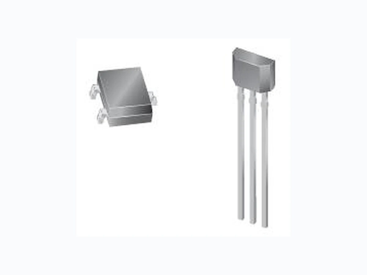
Hall Latch - High Sensitivity eatures and Benefits 5V to 24V rpose F Application Examples A utomotive, Consumer and Industrial Solid-state switch Brushless DC motor commutation Speed detection Linear position detection Angular position detection Proximity detection – Wide operating voltage range from 2. – High magnetic sensitivity – Multi-pu – CMOS technology – Chopper-stabilized amplifier stage stability Superior temperature Extremely low switchpoint drift Insensitive to physical stress – Low current consumption – Output driver with internal pull-up resistor – Tiny SOT23 3L or flat SIP 3L both RoHS Compliant packages 3 pin SOT23 (suffix SO) 3 pin SIP (suffix UA) Functional Block Diagram VDD 1 V 2 . 0 0 M a y . 1 , 2 0 1 2 OUT Voltage Regulatr Chopper Hall Plate GND Rpu Pin 1 – VDD Pin 1 – VDD Pin 2 – GND Pin 2 Pin 3 – OUT Pin 3 ackage – OUT – GND
Hall Latch - High Sensitivity 2 V 2 . 0 0 M a y . 1 , 2 0 1 2 General Description or IC fabricated from mi xed si regul Sc all sta sw Elect specifications and performance have been optimized for ation appl ks to its w ure ra onsu r ic Single In kages are Glossary of Terms Mi iTesla (mT), Units of magnetic flux density: 1mT = 10 Gauss RoHS Restriction of Hazardous Substances S utline Transistor (SOT package) – also referred with the package code “SO” ES E tro- BL Op OP) e flux Rel ease Point (BRP) Magnetic flux density applied on the branded side of the package which turns the output driver OFF (VOUT The S732 is a bipolar Hall effect sens gnal CMOS technology. The device integrates a voltage ator, Hall sensor with dynamic offset cancellation system, hmitt trigger and an output driver with internal pull-up resistor, in a single package. It incorporates advanced chopper bilization techniques to provide accurate and stable magnetic itch points. There are many applications for this HED – Hall ronic Device - in addition to those listed above. The design, commut ications in 5V and 12V brushless DC motors. Than ide operating voltage range and extended choice of temperat nge, it is quite suitable for use in automotive, industrial and c Small Outline T Plast 3-lead pac mer applications. The device is delivered in a ansistor (SOT) for surface mount process or in a Line (SIP 3L flat) for through- hole mount. Both RoHS compliant. ll OT Small O D lec Static Discharge DC Brush-Less Direct-Current erating Point (B Magn tic density applied on the branded side of the package which turns the output driver ON OUT = VDSon) = high)
Hall Latch - High Sensitivity Pin Definitions and Description Type Function SOT Pin № SIP Pin № Name 1 1 DD upply Sup ge pin V S ply Volta 2 3 OUT Output Open Drain Output pin 3 2 GND Ground Ground pin Detailed General Description The S732 exhibits latch magnetic switching characteristics. Therefore, it requir The OUT pin of these devices switches low (turns on) when a magnetic field threshold, BOP. After turn-on, the output voltage is VDSon. Note that the devic es both south and north poles to operate properly . perpendicular to the Hall sensor exceeds the operate point tches, that is, a south pole of sufficient strength to wards the branded surface of the device turns the device on. The device remains on if the south pole is removed (B→0). This ry. When t op po int, and allows clean switching of the output even in the presence of external mechanical vibration and electrical noise. Th eq Po RP) allows an indeterminate output state. The correct sta OP RP Th st r 0mT 0mT e la l atching property defines the device as a magnetic memo he magnetic field is reduced below the release point, BRP , the OUT pin turns off (goes high). The difference in the magnetic erate and release points is the hysteresis, BHYS , of the device. This built-in hysteresis prevents output oscillation near the switching e device behaves as a latch with symmetric operating and release switching points (BOP=|BRP|). This means magnetic fields with uivalent strength and opposite direction drive the output high and low. wering-on the device in the hysteresis region (less than BOP and higher than B te is attained after the first excursion beyond B or B . e SOT-23 device is reversed from the UA package. The SOT-23 output transistor will be latched on in the presence of a sufficiently ong North pole magnetic field applied to the marked face. Output level Output level OUT = High 3 V 2 . 0 0 M a y . 1 , 2 0 1 2 Flux density BOP 18Gs typ OUT = Low OUT = Low UA package - Latch characteristic BOP 18Gs typ BRP -18Gs typ BRP -18Gs typ Flux densit OUT = High BHYSBHYS y SO package - Latch characteristic
Hall Latch - High Sensitivity 4 V 2 . 0 0 M a y . 1 , 2 0 1 2 U que Features technology, S732 is a Hall-effect device with high magnetic sensitivity. This multi-purpose latch meets ments. Th am anced technique possible and contributes to smaller chip size and lower current con ip size is also an important factor to minimize the effect of physical stress. This co Th Abs rameter Symbol Value U n i t s n i Based on mixed signal CMOS most of the application require e chopper-stabilized amplifier uses switched capacitor technique to suppress the offset generally observed with Hall sensors and plifiers. The CMOS technology makes this adv sumption than bipolar technology. The small ch mbination results in more stable magnetic characteristics and enables faster and more precise design. e wide operating voltage from 2.5V to 24V, low current consumption and large choice of operating temperature range according to ”, “K” and “E” specification make this device suitable for automotive, industrial and consumer applications. ol ute Maximum Ratings Pa Supply Voltage VDD 28 V Supply Current IDD 50 mA Out VOUT put Voltage 28 V Out IOUT put Current 50 mA Sto ange TS 150 rage Temperature R -50 to °C Maximum Junction Temperature TJ 165 °C Absolute maximum ratings Oper e Range Symbol ue Units ating Temperatur Val Tem TA o 85 perature Suffix “ E” -40 t °C Tem TA o 125 perature Suffix “ K” -40 t °C Temperature Suffix “ L” TA -40 to 150 °C Exc ay cause perma age. Expo solute rated conditions for extend ity. eeding the absolute maximum ratings m ed periods may affect device reliabil nent dam sure to ab -maximum-
Hall Latch - High Sensitivity V 2 . 0 0 M a y . 1 5 , 2 0 1 2 G eral Electrical Specifications DC less otherwise specified) Parameter Symbol Test Conditions Min Typ Max U n i t s en Operating Parameters TA = 25 ℃, VDD= 2.5V to 24V (un Sup 24 V ply Voltage VDD Operating 2.2 Sup IDD ply Current B < BRP 5 mA Out e VDSon = 2 0mA, 0 V put Saturation Voltag IOUT B > BOP .5 Out IOFF RP VOU 1 10 µA put Leakage Current B < B T = 24V Output R Tr Ω, C L 0. 25 µs ise Time RL = 1k = 20pF Output Fall Time Tf RL = 1kΩ, C L = 20pF 0.25 µs Inte Rpu 9 12 15 rnal pull-up resistor --- kΩ Ma ency FSW 10 ximum Switching Frequ -- - KHz Pac nce RTH le layer (1 3 01 kage Thermal Resista Sing S) Jedec board °C/W Ele Note: The output of S732 will be switched after the supply voltage is over 2.2V, but the magnetic characteristics won't be normal until the s M DC Pa Symbol T est Conditions Min Typ Max Units ctrical specifications upply is over 2.5V. agnetic Specifications Operating Parameters VDD = 2.5V to 24V (unless otherwise specified) rameter O ating Point B OP 10 18 30 G per R -30 -18 -10 G elease Point BRP Hy HYS E spec., T A = 85°C steresis B 36 G Pa Typ Max Units rameter Symbol Test Conditions Min Op BOP 18 erating Point 7 35 G Rel BRP -35 -18 ease Point -7 G Hys BHYS K , T A 85°C teresis spec. = 36 G Operating Point BOP 5 18 40 G Relea BRP -40 -18 -5 G se Point Hys BHYS ec., T A = 150°C 36 teresis L sp G Mag s Ou versus Magnetic Pole netic specification tput Behaviour 批注 [PKU1]: 这个不对, 从图 上看滞后工作区应位于操作 点和释放点之间,建议删了 为它取决于那两个 点, 还要加 K 系列的值, 只 算了 批 KU2]: 这个不对, 从图 上 后工作区应位于操作 点和 点之间,建议删了 为它取决于那两个 点,同时还要加K 系列的值, 只 算了 这项,因 同时 能估 注 [P 看滞 释放 这项,因 能估
Hall Latch - High Sensitivity DC Operating Parameters TA = -40 C to 150 C, V DD = 2.5V to 24V (unless otherwise specified) rameter Test Conditions(SO) OUT(SO) Test Conditions(UA) OUT(UA) Pa So B B > BOP uth pole < BRP High Low Nort B > BOP Low B < BRP High h pole Outp ersus magnetic poleut behaviour v pplication Information s strongly recommended that an external bypass capacitor be connected (in close proximity to the Hall sensor) between the supply(V DD Pin) and ground(GND Pin) of the device to reduce both external noise and noise generated by the chopper stabilization technique. As is shown in the two figures in next page, a 0.1μF capacitor is typical. A It i ed to connect a resistor or a diode in series with the VDD pin. When using a CC Us T herefore, a 100Ω/0.25W resistor for 5V application and a diode for higher supply voltage are recommended. Both solutions provide When a figure 1 The low ce supply voltage V . The diode D1 provides additional reverse voltage protection. The S732 have been optimized for commutation applications in 5V and 12V brushless D The follow figure is the typical application circuit for 3 phase brushless DC motors. F or reverse voltage protection, it is recommend resistor, three points are important: - the resistor has to limit the reverse current to 50mA maximum (VCC / R1 ≤ 50mA) - the resulting device supply voltage VDD has to be higher than VDD min (VDD = VCC – R1*IDD) - the resistor has to withstand the power dissipated in reverse voltage condition (PD = V 2 /R1) ing a diode, a reverse current cannot flow and the voltage drop is almost constant (≈0.7V). the required reverse voltage protection. weak power supply is used or when the device is intended to be used in noisy environment, it is recommended that 3.3 from the Application Information section is used. -pass filter formed by R1 and C1 and the Zener diode Z1 bypass the disturbances or voltage spikes occurring on the devi DD 6 V 2 . 0 0 M a y . 1 , 2 0 1 2 C motors. S732 VDD GND OUT S732 R1:100 Automotive and Severe Environment Prot ection Circuit Typical Three-Wire Application Circuit VDD GND OUT
Hall Latch - High Sensitivity information regarding manufac turability of Hall IC with different soldering processes classified and qualified regarding soldering technology, solderability and moisture sensitivity level according t o ethods: Standard Our products are following test m Reflow Soldering SMD’s (S V 2 . 0 0 M a y . 1 , 2 0 1 2 7 urface Mount Devices) s according to table 5-2) reconditioning of Nonhermetic Surface Mount Devices Prior to Reliability Testing efl 2) Wave S
- IPC/JEDEC J-STD-020 Moisture/Reflow Sensitivity Classification for Nonhermetic Solid State Surface Mount Devices (classification reflow profile EIA/JEDEC JESD22-A113 P r ow profiles according to table oldering SMD’s (Surface Mount Devices) and THD’s (Through Hole Devices)
- EN6 o combined effect of moisture and soldering heat
- EIA Res le mounted devices Iro 0749-20 Res istance of plastic- encapsulated SMD’s t /JEDEC JESD22-B106 and EN60749-15 istance to soldering temperature for through-ho n Soldering THD’s (Through Hole Devices) EN60749-15 • es g temperature for through-hole mounted devices Soldera R istance to solderin bility SMD’s (Surface Mount Devices) and THD’s (Through Hole Devices) S ol ES Electronic semiconductor products are sensitive to Electro Static Discharge (ESD). EIA/JEDEC JESD22-B102 and EN60749-21 derability D Precautions
Hall Latch - High Sensitivity Always observe Electro Static Discharge control procedures whenever handling semiconductor products. Pac P kage Information ackage UA, 3-Pin SIP: 8 V 2 . 0 0 M a y . 1 , 2 0 1 2
Hall Latch - High Sensitivity Package SO, 3-Pin SOT-23: Hall plate lo Notes: 1). PINOUT: Pin 1 VDD P i n 2 O u t p u t 2). All dimension Top View P i n 3 G N D s are in millimeters ; 2.65 1.60 1.70 1 2 1.70 2.10 9 V 2 . 0 0 M a y . 1 , 2 0 1 2 cation Side View End View2.82 3.02 0.08 0.200.70 90 0.70 0.80 0.20 MIN0.00 0.10 0.35 Bottom View of TSOT-23 0.36 0.460.95 0.80 1.50 1.40 Chip 3
Hall Latch - High Sensitivity 10 V 2 . 0 0 M a y . 1 , 2 0 1 2
Ordering Information
Temperature Code Package Code Packing Part No. Pb-free SS SS YES -40°C to 85°C SOT-23 7-in. reel, 3000 pieces/ reel SS732EUA/ SS632EUA YES -40°C to 85°C TO-92 Bulk, 1000 pieces/ bag SS732KSOT/ SS YES 0°C to 125 SOT-23 7-in. reel, 3000 pieces/ reel SS SS YES o 12 -92 Bulk, 1000 pieces/ bag SS732LSOT/ SS632LSOT YES -40°C to 150°C SOT-23 7-in. reel, 3000 pieces/ reel SS732LUA/ SS YES -40°C to 150°C TO-92 Bulk, 1000 pieces/ bag 732ESOT/ 632ESOT 632KSOT -4 °C 732KUA/ 632KUA -40°C t 5°C TO 632LUA