
SRZ ETC
Document overview
- PDF pages: 24
Technical content
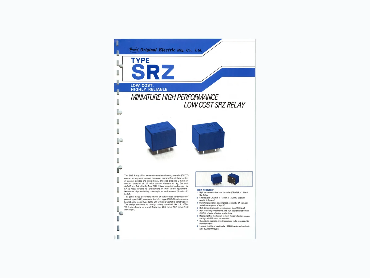
MINIATURE HIGH PERFORMANCE LOW COST SRZ RELAY This SRZ Relay offers extremely smallest size on 2 transfer (DPDT) . contact arrangment to meet the recent demand for miniaturization of control devices and equipment , and also prepares 3 kinds of contact capacity of 2A with contact element of Ag, 3A with AgCdO and 5A with Ag-Aup. SRZ H type covering load current by 5A is most suitable to applications of Hi-Fi audio equipment , because of high sensitivity covering from small current (dry circuit) by 5A. This Series Relay also offers 3 kinds of outside case construction of general type (SRZ), complete Anti-flux type (SRZ-S) and complete hermetically sealed type (SRZ-SH) which is washable construction. The design conforms to foreign safety standard like UL, CSA, VDE, etc. despite very small feature of 20.7 mm x 16.1 mm x 14.3 mm height. Main Features:· 1. High performance low cost 2 transfer (DPDT) P. C. Board Use Relay 2. Smallest size (20. 7mm x 16.1 mm x 14.3mm) and light weight (8.5 grams) 3. Switching operation covering load current by 3A with con tact element system of AgCdO 4. High dielectric strength covering more than 1500 VAC 5. High reliability by complete Anti-flux outside construction (SRZ-S) offering effective productivity 6. Most simplified mechanism to meet massproduction process for high reliability and performance 7. Capacity in magnetic circuit is designed to be suppressed to minimum value 8. Long service life of electrically 100,000 cycles and mechani- cally 10,000,000 cycles ·
REMARKS Connection Diagram ORDERING CODE In case you require your own spe{;s., please contact us. We may arrange your specs., for our acceptance. ~!JR Z H - _§__ - T2 1 2 D ~M L Contact Matedal I Non-lndrcatron: Ag Type 1 : AgCdO . . 2: Ag-Aup Heavy: Duty. typE · ' Rated voltage
1 Non-Indication: 2 Transfer
.I 2030 3VOC M:2 Make contact S: Anti flux type 2060 6VOC 8: 2 Break contact SH: Hermetic Sealed type 2090 9VOC 2120 12VOC 2240 24VOC 2480 48VOC Dimensions Printed Circuit Diagram Fig. 1 Coil Temp. Rise Vs Coil Power Fig. 2 Time Values Vs Coil Power Fig. 3 Life Expectancy a; 50\\\\ -+ -t- -~ ... +1R \\ -t -< -] 8-1.311> Nominal Coil Nominal Nominal Current Voltage (V) DC 3 150 DC 6 75 DC 9 50 DC12 37.5 DC24 19 DC48 10 t (mAl -+Co il Power(W) Coil Resistance ( Q) 180 320 1,280 4,800 Release Time I I 1 -Coil Power (W) Pull-In Voltage (V) less than 75% of nominal voltage Remark: The above values are at 20'C DC 48V available if specified(non-standard) Contact Capacity and Contact Materials SRZ Capacity I Resistive Load AC 120V/DC 24V cos¢= 1 2A Contact I Inductive Load AC 120V/OC 24V cos¢= 0.4 1 Contact Material Ag Specification Coil power Consumption 0.36W (at nominal voltage) Vibration Resistance Contact Resistance Less than 50 m.n Operate Time ab. 5.5 ms (at nominal voltage) Shock Resistance Release Time ab. 2 ms (at nominal voltage) Mechanical Dielectric Strength AC 1 ,500V, 50/60Hz p.m. Life Expectancy Electrical Insulation Resistance More than 100M.n at DC 500V Life Expectancy Temperature range -25°C to +55°C (non-condensing) Max. Operation Temperature rise Less than 40deg (at nominal voltage) Weight Drop-Out Voltage (V) i= 1\\ --; 10 \\ 1\\
- ~ 5 \\ t 0.5 1 1.5 2 -Load Current (A) Max . Continuous Rated Voltage (V) more than 1 Oo/o 1 30% of nominal of nominal voltage voltage SRZ-0-0 1 SRZH·0-0 : 2 JA 5A 1.5 1.5 AgCdO Ag·Aup Vibration 10-55Hz Amplitude 1.5mm Incorrect Operate 10-55Hz Amplitude 1.0mm Incorrect Operate 1 OG More than 10,000,000 times More than 100,000 times Electrical: 1 ,800 times/hour Mechanical: 18,000 times/hour 8.5 grs.
R MINIATURE WIDE VARIETY PO\\NER SRWRELAY This SRW Series Relay was developed to satisfy users' wide applica tion with small installation area on P. C. Board, low cost and wide contact capacity, from our long experience for development of small installation space original Relays. This SRW Series Relay is popularly applicable to control devices and equipments, automobiles, vending machines, household appa ratus, etc. in the output circuit, because of high reliability and performance. This Series Relay offers wide contact capacity of 3A (SRW) with contact element of Ag, 5A (SRWH) with AgCdO on 1 transfer (SPOT) P. C. Board Relay, and can switch large current with small installation space. Outside construction consists of complete Anti-flux type (SRW-S) and complete hermetically sealed type (SRW-SH). SRW-SH type is washable after mounted on P.C. Board ACTUAL SIZE 5A RELAY 5A Relay Main Features: 1. High performance low cost 1 transfer (SPOT) P. C. Board Use Relay 2. Ultra miniature size (18.3mm x 15.2mm x 13.4mm) and light weight 3. High dielectric strength 4. The design conforms to Ul, CSA, VDE, etc. in high per formance 5. Complete Anti-flux construction (SAW-S) offers high and long reliability, and effective productivity 6. long service life of electrically 100,000 cycles and mechani cally 10,000,000 cycles
RE MARKS Connection Diagram O RDERING CODE In case you requ ire y o ur ow n specs., please contact us. We may a rra nge you r specs., for our acceptance. Type Non-1 ndication: Ag 1: AgCdO Non-Indication: 1 Transfer _ M: lMake Contact 8: 1 Break Contact Dimensions II---Yl ~ i w r --~ -1 1 2 D LM + Contact Material H: 5A ~: Anti flux type SH: Hermetic Sealed type 1030: 1060: 1090: 1120: 1240: 1480: 3VDC 6VDC 9VDC 12VDC 24VDC 48VDC Printed Circuit Diagram Fig. 1 Coil Temp. Rise Vs Fig. 2 Coil Power ~~0 e J (I) 50 "';;) <ll v a: ..§. I E ~ 30 i= ~ 'I t E 20 G) t -Coil Power (W) Nominal Coil Time Values Vs Coil Power 10 1 I I Ope;ate Ti me -Release Time -Coil Power (W) 52 • - 183 Fig. 3 Life Expectancy (X10 4 ) 100 :cl00\\1 ' OC2~V \\1 ' ',.,_," 50 \\ 1\\ \\ ~, I\\ ' -~ 1\\', 1\\ ' <ll t 10 \\ \\~ \\ \\ 2 AC100V /OC2.V o.s 1 1.5 2 -Load Current (A) Nominal Nominal Current (rnA) Coil Resistance (rt)± lO% Pull-In Drop-Out Max. Continuous Voltage (V} SRW-S SRWH-S SRW-S DC 3 120 150 25 DC 6 60 75 100 DC 9 40 50 225 DC12 30 37.5 400 DC24 15 19 1,600 Remark: The above values are at 20° C Contact Capacity and Contact Materials Contact Resistive Load AC 120V/DC 24V Capacity Inductive Load AC 120V/DC 24V Contact Material Specification Coil power Consumption (at nominal voltage) 0.36W, 0.45W Contact Resistance Less than 50 mn Operate Time ab. 7 ms (at nominal voltage) Release Time ab. 2 ms (at nominal voltage) Dielectric Strength AC 1,000V, 50/60Hz p.m. Insulation Resistance More than 100Mn at pc 500V Temperature range -25°C to +55°C (non-condensing) Temperature rise Less than 30deg (at nominal voltage) SRWH ·S Voltage (V} Voltage (V) Rated Voltage (V) 20 more than 1 0% 140% of coil less than 75% 80 of coil voltage of coil voltage voltage 180 320 1,280 SRW·S or·SH SRWH-So.r-SH cos <I>= 1 3 5 cos <I>= 0.4 1.5 3 Ag AgCdO Vibration 1-0-55Hz Amplitude 1.5 mm Vibration Resistance Incorrect Operate 10-55Hz Amplitude 1.0mm ). Shock Resistance Incorrect Operate 1 OG Mechanical More than 10,000,000 times Life Expectancy Electrical More than 100,000 times Life Expectancy Max. Operation Electrical: 1,800 times/hour Mechanical: 18.000 times/hour Weight 6 grs.
MINIATURE WIDE VARIETY PO\\NER SRURELAY This SRU Series Relay was developed to satisfy users' wide application with small installation area on P. C. Board, low cost and wide contact capacity, from our long experience for develop ment of small installation space Relays. This SRU Series Relay is popularly applicable to control devices and equipments, automobiles, vending machines, household appa ratus, etc. in the output circuit, because of high reliability and performance. This Series Relay offers wide contact capacity of 3A (SRU) with contactelement of Ag, 7A (SRUH) with AgCdO and 13A (SRUDH) with AgCdO on 1 transfer (SPDT) P. C. Board Relay, and can switch large current with small installation space. Outside construc tion consists of standard encased type (SRU), complete Anti-flux type (SRU-S) and complete hermetically sealed type (SRU-SH). SRU-SH type is washable after mounted on P. C. Board. Main Features: 1. High performance low cost 1 transfer (SPOT) P. C. Board Use Relay 2. Ultra miniature size (19.3mm x 15.6mm x 19mm) and light weight ( 1 0 grams) 3. High dielectric strength covering more than 1500VAC 4. The design conforms to UL, CSA, VDE, etc. in high per formance 5. Complete Anti-flux construction (SRU-S) offers high and long reliability, and effective productivity 6. Long service life of electrically 100,000 cycles and mechani cally 1 0,000,000 cycles
REMARKS ORDERING CODE In case you require your own specs., please contact us. Connection Diagram We may arrange your specs., for our acceptance. S R U H S 1 1 2 D M 1 Contact Material Non-Indication: 1 Transfer B: 1 Break Contacts Non-Indication :for 3A .__ ____ Nominal Voltage H: for 7A DH: for 13A ~: Anti flux type SH: Hermetic Sealed type Printed Circuit Diagram Fig. 1 CD UJ CD ::; iii 103D: 106D: 109D: 112D: 124D: 148D: 3VDC 6VDC 9VDC 12VDC 24VDC 48VDC Coil Temp. Rise Vs Coil Power 60 v 50 I I 40 I 30 I Dimensions Fig. 2 Time Values Vs Coil Power 10 \\ 1 1 lr---;~ Fig. 3 Life Expectancy (XlO•) 100 ACIOOV/DC2<V \\1 ' """-'" 50 \\\\ \\\\ -i= 1\\~ ~ \\
10 I\\' , UJ c: 5
- Release Time \\\\ ~ t 0.2 0.4 0.6 0.8 5-1..3¢ -Coil Power (W) Nominal Coil -Coil Power (W) t 0.5 1 1.5 2 -Load Current (A) Nominal Nominal Current (mA) Coil Resistance (n) Pull-In Drop-Out Max. Continuous Voltage {V) Voltage (V) Voltage (V) Rated Voltage (V) DC 3 120 150 25 20 more than 1 0% 140% of nominal less than 75% DC 6 60 75 100 80 of nominal of nominal voltage DC 9 40 50 225 180 voltage voltage DC12 30 37..5 400 320 DC24 15 19 1,000 1,280 DC48 10 13.7 4,800 3,500 Remark: The above values are at 20° C Co ntact c apac1ty an dC on tact M . I atena s SRU SRU-H SRU-OH Contact Resistive Load AC 120V/OC 24V cos tP = 1 3 7 13 Capacity Inductive Load AC 120V/DC 24V cos tP = 0.4 1.5 3.5 6.5 Contact Material Ag AgCdO AgCdO Specification Coil power Consumption 0.36W,0.45W (at nomtnal voltage) Contact Resistance Less than 50 mn Vibration 10-55Hz Amplitude 1.5 mm Vibration Resistance Incorrect Operate 10-55Hz Amplitude 1.0mm • Operate Time ab. 7 ms (at nominal voltage) Shock Resistance Incorrect Operate 10G Release Time ab. 2 ms (at nominal voltage) Dielectric Strength AC 1 ,500V, 50/60Hz p.m. Insulation Resistance More than 100 Mn at ~C 500V Temperature range -25°C to +55°C (non-condensing) Mechanical More than 10,000,000 times Life Expectancy Electrical More than 100,000 times Life Expectancy Max. Operation Electrical: 1,800 times/hour Mechanical: 18.000 times/hour Temperature rise Less than 30deg (at nominal voltage) Weight 10 grs.
ULTRA MINIATURE HIGH PERFORMANCE OUARELAY This OUA Series Relay has ultra miniature size enough to be perfect for high density packaging despite high reliability and low cost, and also offers smaller installation spcea on P. C. Board. Furthermore, this QUA Series Relay has most rationalized shape and mechanism, enough improved magnetic circuits and also larger value of coil constant (Gc = N 2 /R) to offer high reliability and on wide applications. The Relay specified QUA is 1 transfer (SPOT) contact type Relay prepares 3 types of outside case construction of standard encased type (QUA), complete Anti-flux type (QUA-S) and complete hermetically sealed type (QUA-SH). Contact element employs Ag system for 2A use, AgCdQ system for 3A use and AgPd-Aup system for dry circuits use of crossbar type construction to satisfy wide variety applications like office equipments, business machines, vending machines, various control devices and equipments, security equipments, gas detectors, auto mobiles, etc. Main Features: 1. High performance low cost 1 transfer (SPOT) P.C. Board Use Relay 2. Ultra miniature size (14.8mm x 9.8mm x 10mm) and light weight (3.2 grams) 3. Employment of I. C. Pitch of 2.54mm with Grid Terminal Arrangement 4. Complete Anti-flux construction (0 UA-S) offering high per formance and effective productivity 5. Most simplified shape and mechanism to meet massproduc tion process. 6. Capacity in magnetic circuit is designed to have minimum value by high density packaging 7. Long service life of electrically 100,000 cycles and mechani cally 10,000,000 cycles
REMARKS Connection Diagram ORDERING CODE In case you require your own specs., please contact us. We may arrange your specs., for our acceptance. m---~ 0 u A - s - 1 1 2 D M 1 !h i T -r- -r-T Contact Material Non -Indication: Ag Type 1 : AgCdO ~---_!j 2 : AgPd-Aup Dimensions I 9 11h lr '--Nominal Voltage Non -1 ndication: 1 Transfer M : 1 Make contact f 103D : 3VDC 8 : 1 Break contact ~ J&u:, ~ Anti flux type 106D : 6VDC S: 109D : 9VDC SH : Hermetic Sealed type 112D : 12VDC 7.s_:IJ 1----1 0-----o~ 124D : 24VDC 9.8 1.4 - 14.8 Printed Circuit Diagram Fig. 1 Coil Temp. Rise Vs Fig. 2 Time Values Vs Fig. 3 Life Expectancy Coil Power Coil Power (X10 ) 1oo I 50 i \\ ACIOOV/DC24 V F+ + e 60 v 20 I\\ 1\\ .... T T -;;) 8 E (/) 50 "\\~'7rate]ime 10 40 ~J:f l I E (/) 'iii F 4 c:: sf-0 H &-. _. a; 30 t E 20 2 5 - 1 ¢ -Coil Power (W) -Coil Powe r (W) -Load Current (A) Nominal Coil Nominal Nominal Current (mA) Voltage (V) DC 3 120 DC 6 60 DC 9 40 DC12 30 DC24 15 Remark : The above values are at 20°C Contact Capacity and Contact Materials Coil Resistance (n) Pull-In Voltage (V) 100 less than 75% of nominal 225 voltage 400 1,600 OUA Contact l Resistive Load AC 120V/DC 24V cos¢= 1 2 Capacity I Inductive Load AC 120V/DC24V cos¢= 0.4 1 Contact Material Ag Specification Coil power Consumption 0.36W (at nomanal voltage) Vibration Resistance Contact Resistance Less than 50mn Operate Time ab. 4 ms (at nominal voltage) Shock Resistance Release Time ab 1.5 ms (at nominal voltage) Mechanical Dielectric Strength AC 500V, 50/60Hz p.m. Life Expectancy Electrical Insulation Resistance More than 100Mn at DC 500V Life Expectancy Temperature range -2!f'C + 55°C (non-condensing) Max. Operation Temperature rise Less than 36 deg (at nominal voltage) Weight Drop-Out Max. Continuous Voltage (V) Rated Voltage (V) more than 1 0% 130% of nominal of nominal voltage voltage OUA-0-0 1 OUA-0·0 2 (Cross-bar) 3 1 1.5 0.4 AgCdO AgPd-Aup Vibration 10-55Hz Amplitude 1.5 mm Incorrect Operate 10-55Hz Amplitude 1.0mm Incorrect Operate 10G More than 10,000 times More than 100,000 times Electrical: 1 ,800 times/hour Meehan ical: 18,000 times/hour 3.3 grs.
ULTRA MINIATURE HIGH PERFORMANCE OUA-ZRELAY This OUA-Z Series Relay has ultra miniature size enough to be perfect for high density packaging despite high reliability and low cost, and also offers smaller installation space on P. C. Board Furthermore, this OUA-Z Series Re1ay has most rationalized shape and mechanism, enough improved magnetic circuits and also larger value of coil constant (Gc= N 2/R) to offer high reliabitity and on wide applications. The Relay specified OUA-Z is 1 transfer(SPDT)contact type Relay prepares 2 types of outside case construction of standard enc ased type (OUA-Z) complete Anti-flux type (OUA-Z-S) and com- . plete hermetically sealed type (OUA-Z-SH). Contact element employs AgPd-Aup system for dry circuits use of crossbar type construction to satisfy wide variety applicati ons like telephone office equipments, business machines, vending machines, various control devices and equipments, security equ- ipments, gas detectors, automobiles, etc. . . OUA-Z Series Relay prepares two Kinds of application: OUA-Z is for general use and OUA-ZL is for high sensitivity use. Actual size Main Features: 1. High performance low cost 1 transfer (SPOT) P.C.Board Use Relay 2. Ultra miniature size (14.8mmx9.8mmx10.5mm) and light weight (3.2 grams) 3. Employment of I. C. Pitch of 2.54mm with Grid Terminal Arrangement 4. Complete Anti-flux construction (OUA-ZS) offering high per formance and effective productivity 5. Most simplified shape and mechanism to meet massprodu ction process. 6. Capacity in magnetic circuit is designed to have minimum value by hig'h density packaging 7. Long service life of electrically 500,000 cycles and mecha nically 20,000,000 cycles
- • REMARKS • • In Case you requ1re your own specs .. please contact us. We may arrange your specs .. for our acceptance I ZS - 112L M_ Type Connection Diagram Dimensions OUA-ZS -Nominal Voltage Non-Indication: 1 Transfer M : 1 Make contact 1030: 1060: 1090: 1120: 1240: 3VOC 6VOC 9VOC B: 1 Break contact S: Anti flux type SH: Hermetic Sealed type Printed Circuit Diagram 2.54 5---1¢ View from new feil Nominal Coil Nominal Coil Voltage(V) DC 3 DC 6 DC 9 DC12 DC24 12VOC 24VOC Coil Resistance - D: Standard L: High Sensitive Fig. 1 Coil Temp. Rise-Vs Coil Power f) 60 ~ 50 Q) 40 ~ Q; 30 ~ 20 f- r v v I -+Coil Power(W) Coil Resistance(.Q):h 10% OUA-Z OUA-ZL 20 45 80 180 180 400 320 700 1,280 2,800' Fig. 2 Time Values Vs Coil Power ~ 8 E Qj' E t ' "' ~prate Time li---- Release T1 m e -+Coil Power(W) Pull-in Voltage{V) 70% Max. of nominal voltage Fig. 3 Life Expectancy (10X4 ) CYC LES 1000 600 400 200 (f) 100 w 60 (.!) 40 z 20 ~ 10 w 6 ~ Drop-Out Voltage(V) 10% Min. of nominal voltage ~ buNRdLA~S ~IFE GURVE "' \\. DC24V cos¢= 1 1\\ ' AC100V COS</>= \\) -- 0.1 0.2 04061 2 4 CONTACT RATING(A) Max. Continuous Rated Voltage(V) 130% of nominal voltage Remark: The above values are at 2o·c If other Nom1nal cod voltage w1ll be requ1red, please contact us. Contact Capacity and Contact Materials OUA-Z Contact l Resistive Load AC 120V / DC 24 cos,P = 1 1 Capacity l Inductive Load AC 120V / DC 24 cos¢ =0.4 0.3 Contact Material AgPd-AuP Specification Coil Power OUA-Z abt. 0.45W Vibration Resistance 10 - 55Hz(Dual Amplitude 1.5mm) Consumption OUA-ZL abt. 0.2W (at nominal Voltage) Contact Resistance Less than 50 m Shock Resistance OUA-Z 10G OUA-ZL 6G Operate Time OUA -Z abt. 3.5ms(at nominal voltage) OUA-ZL abt. 6.0ms (at nominal voltage) Mechanical Life More than 20,000,000 ops. Expectancy Release Time OUA-Z & OUA-ZL abt. 1 ms.(at nominal voltage) Dielectric Strength: AC 500V(50 / 60Hz) for 1 minute Electrical Life More than 500,000 ops. Expectancy Insulation Resistance More than 1 00 M at DC 500V Temperature Range ouA -z - 3o·c - + ss·c OUA-ZL - 3o·c ~ + 75·c Max. Repeat Operation OUA-Z 1 00 pulse per second OUA-ZL 60 pulse per second Temperature Rise Less than 36 deg(at nominal voltage} Weight : 3.3 grs.
ULTRA MINIATURE HIGH PERFORMANCE AND RELIABILITY OUB RELAY This OUB Series Relay has very rationalized shape and construc tion in high density packaging to meet massproduction process to offer high reliability and performance despite low cost and small installation space factor. 2 transfer (DPDT) Relay has been requiring complex construction being necessary for much process of assembling and adjusting method on production. Therefore, such comp lex construction has been causing the problems in reliability and cost. To solve such problems, Original Electric Mfg. Co. employed own developed rationalized design on Moving and Fixed contact construction to meet massproduction assembling method and also improved the relative magnetic circuits and coil constant (Gc = N 2 /R) to get larger value than before. Then, OUB Series Relay can offer most rationalized shape and construction against present existing 2 transfer Relays despite high reliability and low cost. This OUB Series Relay is 2 transfer (DPDT) low cost ultraminia ture Relay with P. C. Board Terminals and prepares 3 types of outside case construction of standard type (OUB), complete Anti-flux type (OUB-S) and complete hermetically sealed type (OUB-SH). Contact elements are arranged at Ag contact system for 2A use, and AgCdO for 3A use. The Relay specified OUB is applicable to office equipments, business machines, vending machines, various control devices and equipments, security equipments, gas detectors, automobiles, wire less communications, etc. Main Features: 1. High performance low cost 2 transfer (DPDT) P. C. Board Use Relay 2. Ultra miniature size (17.5mm x 9.8mm x llmm) and light weight (3.5 grams) 3. Complete Anti-flux construction (OUB-S) offering high per formance and effective productivity 4. Most simplified shape and mechanism to meet massproduc tion process 5. Capacity in magnetic circuits is designed to have minimum value in high density packaging Socket 7. Long service life of electrically 100,000 cycles and mechani· cally 10,000,000 cycles
REMARKS In case you require your own specs., please contact us. We may arrange your specs., for our acceptance . Connection Diagram ORDERING CODE .. 0 U B - S - 2 1 2 D M 1 Contact Material I -r- T T f-:-- Non-lndication:Ag Type L_ 1: AgCdo R t d It . Non-Indication: 2 Transfer a e vo age M : 2 Make contacts I S: Anti flux type SH : Hermetic Sealed type 2030 : 2060 : 2090 : 2120 : 224D: 3VDC 6VDC 9VDC 12VDC 24VDC B : 2 Break contact~_ Dimensions Printed Circuit Diagram Fig. 1 Coil Temp. Rise Vs Coil Power Fig. 2 Time Values Vs Coil Power
- n. ltj Ul 8 _§. \\ ~60 I Cll 50 (/) I ii ~Je 0.6 0.6 Fig. 3 Life Expectancy 50 \\ I I [\\' ACIOOV /0024'1 ~ 201 \\1\\ T"l" l~ + + _±Ll I ;;; 30 Cl) 6 E F 4 "\\'-~rate (ime E 10 1J sr-~.JJ~ (/) 0.2 R 2.54 2.54 E 20 Cl) f 8-1 4> -Coil Power (W) Nominal Coil Nominal Nominal Current (mA) Coil Resistance (fl) Voltage (V) DC 3 150 20 DC 6 75 80 DC 9 50 180 DC12 37.5 320 DC24 19 1,280 Remark : The above values are at 20° C Contact Capacity and Contact Materials Contact Resistive Load AC 120V/DC 24V Capacity Inductive Load AC 120V/DC 24V Contact Material Specification Coil power Consumption 0.45W (at nominal voltage) Contact Resistance Less than 50mn Operate Time ab. 5 ms (at nominal voltage) Release Time ab. 1.8 ms (at nominal voltage) Dielectric Strength AC 500V, 50/60Hz p.m. Insulation Resistance More than 1 00 M.n at DC 500V Temperature range -25° C to +55° C (non-condensing) Temperature rise Less than 40deg (at nominal voltage) cos ct> = 1 cos <I>= 0.4 t r-t-2 .2 ;;;
2 N'-·r - Release Time
t - Co il Power (W) 0.5 1 1.5 2 -Load Current (A) Pull-In Drop-Out Max. Continuous Voltage (V} Voltage (V) Rated Voltage (V) 130% of nominal less than 75% more than 10% of nominal of nominal voltage voltage voltage OUB UlJB-D-0 1 2 3 1 1.5 Ag AgCdO Vibration Vibration 10-55Hz Amplitude 1.5mm Resistance Incorrect Operate 10-55Hz Amplitude 1.0mm Shock Resistance Incorrect Operate 10G Mechanical More than 10,000,000 times Life Expectancy Electrical Life Expectancy More than 100,000 times Electrical: 1 ,800 times~hours Max. Operation Mechanical: 18 000 times/hours Weight 3.5 grs.
HIGH PERFORMANCE OUC RELAY This OUC Series Relay was ~eveloped by Original Electric Mfg. Co.'s all technical ability that was cultivated in Electromechanical Relay manufacture for longer period than 20 years, and now offers the smallest size of present existing Relays, of course, in the world despite high performance and reliability. Original Electric Mfg. Co. have been striving to develop High Cost Performance and High Density Packaging Relays to comply with miniatuarization of control devices and equipments and with tendency of synthesized electronic circuits by large scale integrated circuits. From our above mentionecj continuous intention, this · OUC Series Relay was succesfully commercialized to coexist with such tendency of miniatuarization of control devices and of electronic circuits. This Relay specified OUC is 1 transfer (SPOT) Relay which can control load current by 2A despite smallest size in the world. This high performance was realized by improved magneticcircuits and large value of coil constant (Gc = N 2 /R) and extremely rationalized shape and construction to meet massproduction process. Contact element employs Ag System for high performance. This Series Relay prepares 3 types of outside case construction of standard encased type (OUC), complete Anti-flux type (OUC-S) and complete hermetically sealed washable type (OUC-SH) to meet wide variety applications like electronic toys, business machines, office equipments, various control devices and equipments, securi ty equipments, household devices, automobiles, etc. Main Features: 1. High performance low cost 1 transfer (SPOT) P.C. Board Use Relay 2. The smallest size (0. 7mm x 6.8mm x 8.5mm) in the world and light weight ( 1. 7 grams) 3. High performance covering load current by 2A 4. Complete Anti-flux construction (OUC-S) offering high per formance and effective productivity 5. Most simplified mechanism to offer high performance and reliability by massproduction process despite low cost 6. Capacity in magnetic circuit is designed to have minimum value by high density packaging 7. Long service life of electrically 100,000 cycles and mechani cally 10,000,000 cycles
REMARKS Connection Diagram ORDERING CODE In case you require your own specs., please contact us . We may arrange your specs., for our acceptance. 0 u c -S-1 1 2 D M 1 Contact Material IT----fl I -r- L Non-Indication : Ag i}t--ii Type 1: Ag -Aup L::_ ___ ~ Non-Indication : 1 Transfer M :1 Make contact B : 1 Break contact Dimensions t-----9-7-----l 1---s.s---=:1 11 ~11=1 J~l Nominal Voltage 1 \\~ S : Anti flux type 103D : 3VDC SH : Hermetic Sealed type 109D : 9VDC 01 o~~~- ~I t ~ 112D : 12VDC ~ 124D : 24VDC f--s.05 2.5 1.2 Printed Circuit Diagram Fig. 1 Coil Temp. Rise Vs Fig. 2 Time Values Vs Fig. 3 Life Expectancy Coil Power Coil Power (X104 ) 100 e 60 v + + + ~ Ui' 8 a; (/) 50 I E E 40 II Q) 6 10 LI E \\. Operate Time \\ n; F (/) ++ + (5 30 f 4 c:: 5 \\ 1\\ c. I'-.. 0 E -~ l 2.54L 5.08_J 20 2 Q) a; 1- -Release Time 2 f 8- AC HIIV/OOMV 0.5 1 1.5 2. 6-1 ; ~Coil Power (W) ~Coil Pow er (W) ~Load Current (A) Nominal Coil Nominal Nominal Current (mA) Coil Resistance (0) Pull-In Drop-Out Max. Continuous Voltage (V) Voltage (V) Voltage (V) Rated Voltage (V) DC 3 150 20 more than 10% 120% of nominal less than 80% DC 6 75 80 of nominal of nominal voltage DC 9 50 180 voltage voltage DC12 37.5 320 DC24 24 1,000 Remark : The above values are at 20°C c on tact c aoac1tv and c ontact M ate ria ouc OUC-0·0 1 Contact Resistive Load AC 100V/DC 24V cos <I>= 1 2 1 Capacity Inductive Load AC 100V/DC 24V COS</>= 0.4 1 0.5 Contact Material Ag Ag-Aup Specification Coil power Consumption 0.45W (at nominal voltage) Vibration 10-55Hz Amplitude 1.5mm Vibration Resistance Incorrect Operate 10-50Hz Amplitude Contact Resistance Less than 50 rt:~O 1.0mm Operate Time ab. 3.5ms (at nominal voltage) Shock Resistance Incorrect Operate 10G Release Time ab. 1.8 ms (at nominal voltage) Dielectric Strength AC 500V. 50/60Hz p.m . Insulation Resistance More than 1 00 Mn at DC 500V Temperature range -25° C to +55° C (non-condensing) Mechanical More than 10,000,000 times Ufe Expectancy Electrical More than 100,000 times Ufe Expectancy Max. Operation Electrical: 1 ,800 times/hours Mechanical: 18,000 times/hours Temperature rise Less than 50deg (at nominal voltage Weight 1.7 grs.
SUPER ULTRA MIN/TELEPHONE RELAY ACTUA L SIZE This OUC Series Relay was ~eveloped by Original Electric Mfg. Co.'s all technical ability that was cultivated in Electromechanical Relay manufacture for longer period than 20 years, and now offers the smallest size of present existing Relays, of course, in the world despite high performance and reliability. Original Electric Mfg. Co. have been striving to develop High Cost Performance and High Density Packaging Relays to comply with miniatuarization of control devices and equipments and with tendency of synthesized electronic circuits by large scale integrated circuits. From our above mentioned continuous intention, this OUC Series Relay was succesfully commercialized to coexist with such tendency of miniatuarization of control devices and of electronic circuits. This Relay specified OUC-T is x- bar contact type Relay which can control load current by 1 A despfte smallest·size in the world. This high performance was realized by improved magnetic circuits and large value of coiJ constant (Gc = N 2 /R) and extremely rationalized shape and construction to meet massproduction process. Contact element employs Ag Pd-Aup System for high performance. This Series Relay prepares 2 types of complete Anti-flux type (OUC-S) and complete hermetically sealed washable type (OUC-SH) to meet wide variety applications like business machines, office equipment, various control devices and equip ment, security equipment, telecommunication equipment. Main . Features: 1. High performance low cost l transfer (SPOT) x- bar contact type P.C. Board Use Relay and light weight ( 1. 7 grams) 3. High performance covering load current by lA 4. Complete Anti-flux construction (0 UC-S) offering high per formance and effective productivity 5. Most simplified mechanism to offer high performance and reliability by massproduction process despite low cost 6. Capacity in magnetic circuit is designed to have minimum value by high density packaging 7. Long service life of electrically 10,000,000 cycles and mechanically 50,000,000 cycles
REMARKS Connection Diagram ORDERING CODE In case you require your own specs., please contact us. We may arrange y_our specs., for our acceptance. Type Contact Material Ag Pd-Aup lj----fl ,-=r--~-112DLM Non-Indication: 1 Transfer M : 1 Make contact B : 1 Break contact '---- --- Nom inal Voltage S : Ant i flux type 103D : 106D : 109D : 112D : 124D : 3VDC 6VDC 9VDC SH : Herme tic Sealed type Printed Circuit Diagram
- • •n :!!! + + -tll l2. ~Ls.~J 6-1¢ Nominal Coil 12VDC 24VDC Fig. 1 Coil Temp. Rise Vs Coil Power e 60 v q) (/) 50 I a: ~ 40 :I II iii Qi 30 E 20 q) t L.._ -Coil Power (W) Dimensions OUC·T-S Fig. 2 Time Values Vs Coil Power .§. E I\\ Operate Time 21--+-::±~~=4:-l - Release T im e -Coil Power (W) Fig. 3 Life Expectancy (X10 } 100
50 I I ""'''JV/DC24V
E 10 f-+-4\\-+-+- (/) 5 1\\ \\ -~ 1\\ 1\\ ! 2 ACIQ'lY/0CZ4Y 0.5 1 1.5 2. -Load Current (A) Nominal Nominal Current (rnA) Coil Resistance (0) Pull-In Drop-Out Max. Continuous Voltage (V) Voltage (V) Voltage (V) Rated Voltage (V) DC 3 150 20 DC 6 75 80 DC 9 50 180 DC12 37.5 320 DC24 24 1,000 Remark : The above values are at 20° C Contact Capacity and Contact Material Contact Resistive Load AC 100V/DC 24V Capacity Inductive Load AC 100V/DC 24V Contact Material Specification Coil power. Consumption 0.45W (at nominal voltage) Contact Resistance Less than 50 mO Operate Time ab. 3.5ms (at nominal voltage) Release Time ab. 1.8 ms (at nominal voltage} Dielectric Strength AC 500V, 50/60Hz p.m. Insulation Resistance More than 1 00 MO at DC 500V Temperature range -25° C to +55° C (non-condensing) Temperature rise Less than 50deg (at nominal voltage) cos cJ> = 1 cos cJ> = 0.4 less than 80% more than 10% 120% of nominal of nominal of nominal voltage voltage voltage OUC-T 0.5 Ag Pd-Aup (X-Bar) Vibration 10-55Hz Amplitude 1.5mm Vibration Resistance Incorrect Operate 10-50Hz Amplitude 1.0mm Shock Resistance Incorrect Operate 10G Mechanical More than 50,000,000 times Life Expectancy Electrical More than 10,000,000 times Life Expectancy Max. Operation Electrical: 1,800 times/hours Mechanical: 18.000 times/hours Weight 1.7 grs.
OUD types are miniature size, low cost, for printed circuit board and and 1 transfer. Contact materials used areAg or Au overlaid Ag base for dry circuit to 3A (crossbar contact) and AgCdO for 7 A and 1 OA. Insulation distance is kept 4.0 mm which is the widest in this miniature class, and resisisting pressure of insulation is suffi ciently passed AC 4000V. "High sensitivity type"and"Keep type" are also prepared in the series. Plastic material used is passed UL standard, and insulation lass is" E". nti-flux type (S) can completely shut flux even in soldering process by automatic soldering machine machine and Her meteic sealed type(SH) can wash in water. Thus QUO type is said a very original relay. After washing,in case of need, the inside of relay can be ventilated by taking out the knob on the case head of relay. ®E58304(S) .a. FEATURES 1. LOW COST, HIGHLY RELIABLE, FOR P.C. BOARD, 1 TRANSFER 2. MINIATURE SIZE:16.0X 21.0X 14.2 (m jm) 3. DRY CIRCUIT TO 1 OA 4.1NSULATION DISTANCE: MORE THAN 7.5MM 5. CSA AND JAPANESE STANDARD ALLOWABLE 6. COMPLETE ANTI-FLUX AND HERMETIC SEALED TYPE. 7. UL A PROVED File No E58304
Nonindication: for 3A M:for 7A H :for 1 OA K : Keep type L :High sensitive type E :Economica I type Printed Circuit Diagram i f-. Connection Diagram 11 os ol ~OJ L l__Nonindication:Ag 1 :AgCdO 2: Au overlaid Ag Nonindication: 1 Transfer M: Make contact only B : Break contact only S: Anti flux type SH: Hermetic Sealed type 1030: 30C 1060: 60C 1090: 90C 1120:120C 1240 :240C 1480:480C nl Dimensions 0 U D - S Fig. 1 Coil Temp. RiseVs Fig.2 Tine Values Vs Coil Fig.3 Life Expancy Curve Coil Power Curve Power Curve (with Relays mounted on P.C Boards) X103 § 1000 l 500 :1.\\' .... ~ ~' I'... -1.0-1.2~ I cr 80 I If II I \\ I I T TT T 17 : a: u I!! 5.08 12.70 E Gl t ..; -+Coil Power(W) S pacification 0.36W (OUD) 0.45W (OUDM & H) Vlbrltion Durability 10-55Hz Ampliu-· de 1.5mm Incorrect Oper ata 10-55Hz Amplitude 1.0mm Incorrect Operate 1 OG Meche- more than 20,000,000 niCII times 8fe tancy Uect· riel! Ma x. Operetion DUD-more than 500,000 times. OUDM-more than 100.000 time, OUDH·more than 100,000 times at nominal lood. 8ectrical: 1,800 times/hour Mechanical: 18,000 times/hour I I I II I ~ .ll 11.JT Opert~te T1me - 1""'+-
0 Release Time I I I I
-+ Coil Power 100 !':-.. 1 2 3 4 5 6 ( 0 U D) 2 4 6 8 10 12 ( 0 U D H ) 1 . Contact Loed : Resistive 2. OUDH Relay OUD Relay Nominal Nom inal Nominlll Coil Pull-In Drop-0~ M.ex.COn· H & M tinuous Voltlgi(V) Current{IJIA) '*iatancellll Voltege{V) Voltage(V) v~:~IVJ DC3 120 25 20 less than 75% more than 1 0 '!' 160%of DC6 60 100 80 of nominal of nominal volt nominal volt- DC9 40 225 180 voltage -age age DC12 30 400 320 DC24 15 1600 1280 DC48 14 3500 3500 120% eRemark : The above values are at 20' C. Remark: In case of High sensitive type. pull-ln Voltage is less than 65% and Drop-Out Voltage is more than 6% . Contact Capacity Resistive Load 120VAC /30VDCcos ¢ = 1 Inductive Load 120VAC /30VDC cos ¢ =0.4 OUD OUDM . OUDH
MINIATURE HIGH RELIABILITY AND PERFORMANCE COMMUNICATION OMF RELAY This OMF Series Relay was developed to be utilized mainly to applications requiring high reliability and performance like com munication equipments, Hi-Fi audio apparatus, control devices and equipments, etc. in versatile field. This OMF Series Relay offers super ultra miniature size on 2 transfer (DPDT) contact arrangement despite high reliability and performance by massproduction process, and constitutes one remarkable type among our super ultra miniature size Series Relays. The Terminals are arranged at inch-size of I. C. to meet 16 Pins I. C. Socket. Contact element employs AgPd-Aup system of crossbar type construction to get higher performance at low level operation. This Series Relay also offers two kinds of outside construction of Anti-flux type (OMF-S) which keeps the Relay from invading Solder flux into the Relay Case, and complete hermetically sealed type (OMF-SH) which has washable construction. OMF-SH Relay can be washable after mounted on P. C. Board, too. Main Features: 1. Ultra miniature size high performance low cost 2 transfer (DPDT) P. C. Board Use Relay 3. AgPd-Aup contact elements of crossbar type construction for higher performance at low level operation 4. Complete Anti-flux construction (OMF-S) 5. 2 makes and 2 breaks contact arrangement available if speci fied 6. Long service life of electrically 500,000 cycles and mechani cally 10,000,000 cycles
REMARKS Connection Diagram ORDERING CODE In case you require your own specs., please contact us . We may arrange your specs., fo r our acceptance.
0 M F -S-212DM
I Type T 1 1_Non-lndkation:2Transfer M : 2 Make contacts B : 2 Break contacts Rated voltage .-----~--· Dimensions S : Anti-flux type SH : Hermetic Sealed type Printed Circuit Diagram 8-1<1> Nominal Coil 203D : 205D: 206D: 209D: 212D: 224D: 3VDC 5VDC 6VDC 9VDC 12VDC 24VDC Fig. 1 Coil Temp. Rise Vs Coil Power e 60 iii 8. 30 E t -Coil Power (W) Fig. 2 Time Values Vs Coil Power U)ar--t-+-+-+--+---lH ..§. ~ 6 ' ~'-.Operate Time ' ~ 4~~+-+~~T'l::±-t--iH - Release Time -Coil Power (W) Fig. 3 Life Expectancy 50 \\ I l I\\ ~I OOV I OC2<V ~ 20 1\\ TT E 10 1J -~ s r---\\L.J.~;~, iii \\ ll ! 2 \\J t ~H_tHlH 0.5 1 1.5 2 -Load Current(A) Nominal Nominal Current (mA) Coil Resistance (fl) Pull-In Drop-Out Max. Continuous Voltage (V) Voltage (V) Voltage (V) Rated Voltage (V) DC 3 200 15 DC 5 111 45 less than 70% of nominal DC 6 NO 60 voltage DC 9 64 140 DC12 43 280 DC24 22 1,070 Remark: The above values are at 20°C Contact Capacity and Contact Materials Contact Resistive Load AC 120V /DC 28V Capacity Inductive Load AC 120V/DC 28V Contact Material Specification Coil power Consumption 0.45W (at nominal voltage) Contact Resistance Less than 50mn Operate Time ab. 5ms (at nominal voltage) Release Time ab. 1.8ms (at nominal voltage) Dielectric Strength AC 500V, 50/60Hz p.m. Insulation Resistance More than 1 00 Mn at DC 500V Temperature range -30° to +50° C (non-condensing) Temperature rise Less than 65deg (at nominal voltage) cos <P = 1 cos <P = 0.4 Vibration Resistance Shock Resistance Mechanical Life Expectancy Electrical Life Expectancy Max. Operation Weight more than 5% 120% of nominal of nominal voltage voltage OMF 0.5A AgPd-Aup Vibration 10-55Hz Amplitude 1.5 mm Incorrect Operate 10-55Hz Amplitude 1.0mm Incorrect Operate 10G More than 10,000,000 times More than 500,000 times Electrical: 1 ,800 times/hour Mechanical: 18,000 times/hour 3.8 grs. I
MINIATURE HIGH PERFORMANCE HIGH POWER OM/ RELAY This OMI Series Relay has smallest size enough to be perfect for high density packaging to be suitable for applications where small board space and height are requested. This OM I Series Relay also offers extremely high performance by withstanding high dielectric strength of 5000VAC and surge resistive voltage more than 10KV. This OMI Series Relay conforms to TV-3 of UL, CSA and VDE in addition to Japanese Safety Standard. This OMI Series Relay has 2 types on contact form of 1 transfer (SPOT) and 2 transfer (DPDT) and prepares 2 types on coil sensitivity of general use sensitivity type (OMI) and high sensitivity type (OMI -L) in lower power consumption to meet with users' versatile applications. Furthermore, hermetically sealed high per formance type (OMI-SH) is also available for severe environmental applications in addition to general Anti-flux type (OMI-S). Her metically sealed type offers washable construction. Contact element system employs AgCdO for 1 OA on 1 transfer type, and AgCdO for 5A and AgCdO-Aup for 5A on 2 transfer type. Main Features: 1. High performance low cost P. C. Board Use Relay 2. Miniature and slim type offering small board space factor 3. High dielectric strength of 5000VAC and surge resistive volt age more than 10KV 4. Design conforms to foreign safety standards like U L, CSA, VDE, etc. 5. Anti-flux construction offers high and long reliability, and effective productivity. 6. Long service life of electrically 100,000 cycles and mechani cally 5,000,000 cycles
REMARKS Connection Diagram ORDERING CODE In case you require your own specs., please contact us . We may arrange your specs., for our acceptance. OMI-S-112LM1 SPOT DPDT T T I TTL Lcontact Material S: Anti-flux SH : Hermetic Sealed type Printed Circuit Diagram 103,203 : 105, 205 : 106,206: 109,209: 112,212: 124,224: 148, 248 : (SPOT) (DPDT) Voltage 3VDC 5VDC GVDC 9VDC 12VDC 24VDC 48VDC Fig. 1 Contact Current vs Ambient T emp. -. -. 0 70 ~--~ ~ - Non-1 ndication: AgCdO 1: Aup Non indication: Transfer M: Make contacts B : Break contacts Coil Resistance D : Standard Dimensions·OlJ ~ - ~ L D -.-- L : High Sensitive Fig. 2 Operating Range (SPOT, 10A) ~28. 9~ .. ·~ na~~+ Fig. 2 Operating Range (OPDT, ·sA) 2.o 1-H~~~HHI--HHHH ~ 1.6 > ! 1.4 1!'1.6
- ;;c g.1.4 :E1.2 1.8 5.08 5.08 30 8-1.54> 0 0 1 2 3 • 5 6 7 8 9 10 Contact Current (A) Nominal Coil (CoilenervizedwithnominaiYOitage) .!! 1.0 g ~ 0.8 j o6 =H~..Iillaf-+~4-1-.::!i 0 10 20 30 40 50 60 70 80 90 100 110 Ambmet Temperature I' C) - Non Carrying Current Contact
- --· 5A Carrying Current Contact - ·- 1 OA Carrying Current COntact 0 10 20 30 40 50 60 70 1!9 90 100 110 Ambient Tempe rature rcl - Non Canytng Current Contact
- ····-SA Carrying current Contact Nominal Nominal Current (mA) Coil Resistance (.\\1) Pull-In Drop-Out Max. Continuous Voltage (V) Voltage (V) Voltage (V) Rated Voltage (V) DC 3 240 176 12.5 17 DC 5 138 106 36 47 less than 70% more than 1 0% DC 6 120 88 50 68 of nominal of nomina1 See Fig. 2 DC 9 78 58 115 155 voltage voltage DC12 60 44 200 270 DC24 29 22 820 1,100 DC48 14.5 11 3,300 4,400 Remark : The above values are at 20° C Contact Capacity and Contact Materials SPOT DPDT Contact Resistance Load DC30V I AC 24'0V 10A 5A Capacity Inductive Load AC 120V Contact Material Specification Coil power Consumption (at nominal voltage) Contact Resistance Operate Time Release Time Dielectric Strength Insulation Resistance Temperature range 0.72W 0.53W Less than 50Mn ab. 15ms (at nominal voltage) ab. 7 ms (at nominal voltage) AC 5,000V, 50/60Hz p.m. More than 100Mn at DC 500V -30°C to +55°C (non-condensing) 1/4 HP 10A 1/8 HP 5A AgCdO -Aup AgCdO Surge Strength 10 KV Vibration Resistance Shock Resistance Max. Operation Vibration 10-55Hz Amp I itude 2 mm Incorrect Operate 10-55Hz Amplitude 1.0mm Incorrect Operate 10G More than 5,000,000 times More than 100,000 times Electrical ~ 1 ,800 times/hour Mechanical: 18 000 times/hour
.MAIN FEATURES
- SRE and SRET cover load current from 3A upto 15A on Pole Numbers of 1, 2 and 4 in spite of very small construction.
- High reliability and long service life.
- High Sensitivity and Fast Operation even in small Power Consumption
- Strong construction for Vibration and shock. eUL File No.E58304(S) e SRET type conforms with UL and CSA .
- RATING SPECIFICATIONS . Current{mA) Coil Operate Release Max. Allowable 50Hz 60Hz Resistance( ohm) Voltage(V) Voltage(V) Voltage(V) e 6 234 200 10 12 117 100 43 24 58.5 50 160 30% Min. AC 50 28.1 24 600 100/115 14.1 12/13.6 2900/3900 200/240 9.4 8/5.5 15000 SO% Max. 110% Note : Current and Coil Resistance values are 6 150 40 measured under 20"C of Coil Temperature. 12 75 160 10% Min. Tolerance should he 415% -20% for AC Use DC 24 36.9 650 and ±15% for DC Use and ±15% for Coil 48 18.5 2600 Resistance. 100!110 9.1/10 10000/llOOO 1, 2 Poles(SRE) 4 Poles(SRE) 1. 2Poles(SRE) 1 Pole(SRET) 2 Poles ( S RET) R Load L Load R Load L Load R Load L Load R Load L Load R Load L Load m Rating AC220V/5A 2A AC220V/3A O.SA AC220V/7A 3.5A AC110V/15A lOA ACUOV/lOA 7.5A Load DC24V/5A 2A DC24V/3A 1.5A DC24V/7A 3.5A DC24V/15A 7A DC24V/10A SA Current SA 3A 7A 15A lOA Allowable Voltage AC250V DC125V AC250V DC125V AC250V DC125V AC250V DC125V AC250V DC125V Max. Current SA SA 3A 3A 7A 7A lSA 15A lOA lOA I AI llOOVA 440VA 660VA ISO VA 1540VA 170VA 1700VA llOOVA UOOVA 830VA Capacity j lSOW 60W 90W 4SW 170W ssw 360W 170W 240W 120W DC Min. Load - DCIV lmA - - - Contact Material AgCdO Ag AgCdO AgCdO AgCdO Note: L Load: cos¢= 1 L Load: cos¢=0.4 L/R=7ms If Ianger contact capacity will be required, please contact us .
- TYPE CONSTRUCTION :TYPE SRE SRET II : NO.OF POLE 1 : 1 p 2 : 2 p 4:4p J.iijj I ni : COIL VOLTAGE Code Voltage Coil Colour OlD 6VDC Copper 020 12VDC Green 030 24VDC Yellow 040 48VDC Gray
050 I OOVDC Blue
060 IIOVDC Blue
D II Code Voltage
01 A 6VAC
1·1§1·1 III I N II v I II VI I Coil Colour ,--J NO MARK : Regular Type Copper Green Yellow Gray Blue Orange N : TERMINALS No Mark : Soldering Type Plug-In Use P : P.C.B.Terminal F : Mount Frange Type S : Special Type VI : CONTACT CAPACITY (under development) Orange SPECS. MENTIONED IN THIS CATALOGUE SHOULD BE CHANGED WITHOUT ANY NOTICE. Orange
.SPECIFICATIONS
- Contact Resistance : 50 milli ohm Max.
- Operate Time : 20 milli sec. Max.
- Release Time ·: 20 milli sec. Max.
- Max. Operations : Mechanically······18, 000 operations/hour Electrically ··· ··· 1, 800 operations/hour
- Insulation Resistance : 100 Meg ohm Min. at DC500V
- Dielectric Strength : AC1500V 50 /60Hz for one minute ( ACIOOOV between non continous contacts)
- Vibration : 10 - 55Hz Double Amplitude lmm (Operation Error······I0-55Hz Double Amplitude lmm)
- DIMENSION
- Shock : 1 OOOm / s 2 ( abt.l OOG) (Operation Error······200m/s 2 abt. 20G)
- Service Life : Mechanically······AC 50,000,000 operations DCIOO, 000,000 operations Electrically ······1, 2 P 500,000 operations 4P 200,000 operations (at Rating Load)
- Operating Tern. : -10- + 55oC (No condensing)
- Operating Humidity : 45 - 85% RH
- Weight : abt. 35grs . {3.5.7 A) SRE 2 Poles {3A) SRE 4 Poles ( 5. 7 A) SRE I Pole 0.8 35.5MAX 41MAX (BOTTOM VIEW ) {10A) SRET 2 Poles (15A) SRET I Pole (BOTTOM VIEW ) .SRE , SRET LIFE CURVE 500 100 X ~ 50 ::::i 100 0 50 X ::::i 100 AC nov R Load .,.., :"1'-o. R Load 1 2 Current( A) F Life 2 P(SRET} II II l OC24V R Load
- "- !/1 AC110V lW:Jl1 [I. R Load !Wvi=AC110V ~cn;1n' OE; (LA 7ms) 0 2 4 6 8 10 12 14 16 18 20 Current( A) 500 100 X Q) 50 ::::i ;--0 1000 500 X ::::i 100 Life _ l I I f I =I= I=,_ 4 P(SRE) ~ 1'- I I I ~~~ AC 1 iov c~s¢~0 .... ~ Al220V o630v cos¢=0.4::: ~ LIR 7ms ~~ O!i 1.5 Current( A) ~- Life I P ( SRETl= II II AC110V R Load DC24V - \\'IIi ~~ 11 R Load J\\.1 ~ ~ V7ms)~ f.c110V (cos; 0.4) 0 2 4 6 8 10 12 14 16 18 20 Current( A) X ::::i 500 100 (BOTTOM VIEW ) r:hi ~-:r r"5""-J (BOTTOM VIEW ) (BOTTOM VIEW ) .P.C .B . LAYOUT If 3 Poles type will be required, please contact us. l•7 ---'~ T~' · Life t I l ! I l I I 1.2 P (SRE). ~ Af IIOV R Load -t-- T DC24V R Load rrrr r-+-1-- 3 4 !i Current( A) 3,5,7A 500 100 X Q) 50 ::::i Life
1 P/2P
- 15A j I I I ! I I - 1.2 P ( SRE A~t :oJ ~s¢ =~ 4 1- ~~J AC220V cos·~-04~ DC24V LiR=7ms I Ill Current( A) 9 Original Electric Mfg. Co., Ltd. Kida Bldg., 2-13, 1-Chome, Yushima, Bunkyo-ku, Tokyo, Japan . Tel: Tokyo(255) 2984 Telex: Tokyo(222)4650 Cable Address"OLRIC MFG"TOKYO PRINTED IN JAPAN I