
SR2 TEC
Document overview
- Manufacturer or author: Provided By www.digicamel.com(FREE DATASHEET DOWNLOAD SITE)
- PDF pages: 2
Technical content
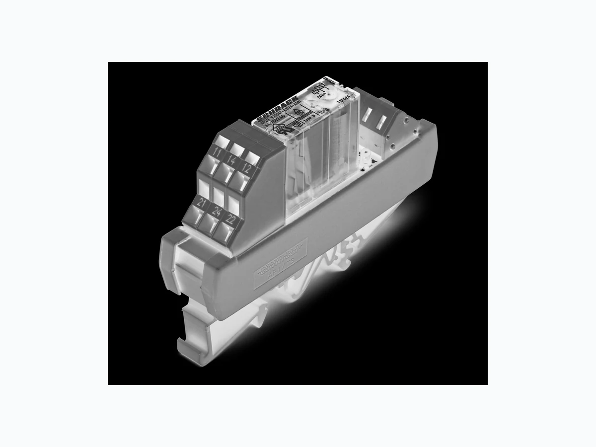
10-2012, Rev. 1012 www.te.com © 2011 Tyco Electronics Corporation, a TE Connectivity Ltd. company Datasheets and product specification according to IEC 61810-1 and to be used only together with the ‘Definitions’ section. Datasheets and product data is subject to the terms of the disclaimer and all chapters of the ‘Definitions’ section, available at http://relays.te.com/definitions Datasheets, product data, ‘Definitions’ sec- tion, application notes and all specifications are subject to change. SCHRACK General Purpose Relays Force Guided Relays n 2 pole relay with force guided contacts according to EN50205 n DIN rail mounting Typical applications contact monitoring in railway, elevator and machine controls Approvals Relay SR2M: VDE, UL, TUV, CQC Module SR2Z: CE Technical data of approved types on request Contact Data Contact arrangement 2 form C (CO) contacts According EN50205 only 1NO / 1NC (11-14 and 22-21 or 12-11 and 21-24) shall be used as force guided contacts. Rated voltage 250VAC Max. switching voltage 250VAC Rated current 6A Contact material AgNi Contact style single contact, force guided 1 form A + B, 1 NO + 1NC type A according to EN 50205 2 form C, 2CO type B according to EN 50205 Min. recommended contact load 5V/10mA Initial contact resistance ≤100mΩ at 1A, 24VDC ≤20Ω at 10mA, 5VDC Frequency of operation, with/without load 6/300min-1 Contact ratings, IEC60947-5-1, on 1 form A (NO) contact AC15-3A DC13-6A Mechanical endurance 10x10 6 operations Coil Data Coil voltage range 24VDC Operative range, % of rated coil voltage 90 to 110% of Urtd Release voltage (+23°C) 10% of Urtd Limiting voltage, % of rated coil voltage 110% Max. coil power 700mW Input circuit LED Insulation Data Initial dielectric strength between open contacts 1500V rms between contact and coil 4000Vrms between adjacent contacts 2000Vrms Clearance/creepage between open contacts microdisconnection between contact and coil ≥8/8mm between adjacent contacts ≥1/1mm Insulation to EN 50178, type of insulation between contact and coil reinforced between adjacent contacts basic Other Data Material compliance: EU RoHS/ELV, China RoHS, REACH, Halogen content refer to the Product Compliance Support Center at www.te.com/customersupport/rohssupportcenter Ambient temperature range for mounting/handling 0 to 40°C in operation -25 to 50°C Terminal type screwless clamp connectors Wire cross section solid wire 2.5mm2 stranded wire 2.5mm2 stranded wire with bootlace crimp 1.5mm2 Mounting position any Weight 50g Packaging unit 2 Force Guided Relay on DIN-rail SR2 Z F-SR2Z-A
10-2012, Rev. 1012 www.te.com © 2011 Tyco Electronics Corporation, a TE Connectivity Ltd. company Datasheets and product specification according to IEC 61810-1 and to be used only together with the ‘Definitions’ section. Datasheets and product data is subject to the terms of the disclaimer and all chapters of the ‘Definitions’ section, available at http://relays.te.com/definitions Datasheets, product data, ‘Definitions’ sec- tion, application notes and all specifications are subject to change. SCHRACK Force Guided Relay on DIN-rail SR2 Z (Continued) General Purpose Relays Force Guided Relays Terminal assignment S0532-A Module width 20 mm Module length 87 mm Dimensions Fit onto mounting rails according to DIN EN 60175 S0533-A Product code structure Typical product code SR2Z Y 024 Type SR2Z Relay with force guided contacts on DIN-rail SR2 Z Contact configuration Y 2 form C (CO) contacts Coil DC Coil code = rated coil voltage (e.g. 024=24 VDC) Other types on request Product code Type Contact configuration Coil Part number SR2ZY024 2-pole module 2 form C (CO) contacts 24VDC 9-1415536-1