

 Download PDF
SPVE ETC2
Document overview
- Manufacturer or author: Provided By www.digicamel.com(FREE DATASHEET DOWNLOAD SITE)
- PDF pages: 5
Technical content
Features
For detecting batteries in DSCs and LCDs For detecting the position of lids in mobile phones and laptop computers For detecting media in portable CD/MD players and 1/2 inch FDDs Products Line Poles 1 1 h=3.8 h=4.1 h=4.8 h=5.2 h=5.5 h=3.3 h=4.75 Positions Products No. Slider height ʢmmʣ h1=3.5 h1=3.8 h1=4.5 h1=4.9 h1=5.2 h1=3.0 h1=4.45 ON start positionʢmmʣ h2=2.5 h2=2.9 h2=3.6 h2=4.0 h2=4.3 h2=2.0 h2=3.35 Total travelʢmmʣ Location lug Standard Low- profile Mounting method Terminal style Drawing No. For PC board ʢReflowʣ Operating life 0.1A 30V DC 0.3N max. 500mЊ max./1Њ max. 50,000 cycles Ratingʢmax.ʣʢResistive loadʣ Items Specifications Contact resistance ʢInitial performance/After lifetimeʣ Operating force 50,000 cyclesʢ0.1A 12V DCʣ Without load With load Typical Specifications SPVE110100 SPVE110600 SPVE110401 SPVE110801 SPVE110200 SPVE110900 SPVE111300 SPVE111200 SPVE210100 SPVE210200 Without With Without With Without With ʕ Minimum packing unitʢpcs.ʣ 2,800 2,200 2,000 2,800 2,000 1. The dimensions indicates the standard type with a locating lug. 2. Additional switches not included in the above list are also available. Contact us for details. Notes For other detailed specifications, see P.303 For specifications for the taping package, see P.307
Applications
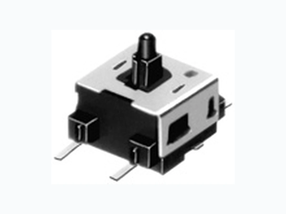
Compact One-way Operation Type Detector Switch SPVE Series
Unit:mmDimensions Style PC board mounting hole dimensionsNo. 0.7 3.051.2 1.5 ø1.35 hole 0.7 Standard type Reflow pattem 0.7 1.2 0.7 2.2 (4.4) (4) (3.2) Oblong hole Low-profile type Low-profile typeStandard type Low-profile typeStandard type 3 1 Terminal LayoutʢViewed from Direction Aʣ 23 12 Circuit Diagram Location lug ON, OFF starting position 0.07 2.30.5 C0.2 0.75 0.68 ø1.3 Terminal No. 1 3 11 1.5 3.4 0.3 0.3 h A Total travel position 3-0.3 2.2 1. 3 1. 3 1. 6 1.1 3.4 0.1 Terminal No.1 4.4 0.07 1.80.5 3.1C0.2 0.75 0.68 h A ON, OFF starting position Total travel position Compact One-way Operation Type Detector Switch SPVE Series
2Њ max. 50,000 cycles 5Њ max. ʢ1mA 5V DCʣ 50,000 cycles 5Њ max. for 1 min. SSCM 0.5N 0.5N for 1 min. 500mЊ max. SPVG 50mA 20V DC 10N Ŗ40ʶ2ˆ for 96h 100,000 cycles 1Њ max. ʢ50mA 20V DCʣ 100,000 cycles 1Њ max. SPVN max. 50,000 cycles 5Њ max. ʢ1mA 5V DCʣ 50,000 cycles 5Њ max. Ŗ20ʶ2ˆ for 96h Series Items Operating temperature range Ratingʢmax.ʣ ʢResistive loadʣ Electrical performance Mechanical performance Durability Environmental performance Initial contact resistance Insulation resistance Voltage proof Robustness of terminal Robustness of actuator Operating life without load Operating life with load Cold Dry heat Damp heat Resistance to soldering heat Manual soldering Dip soldering Reflow soldering Vibration SPPB 0.1A 30V DC ʢ0.1A 30V DCʣ 50,000 cycles 2Њ max. 50,000 cycles 2Њ max. SPVE SPPW8 Ŗ10ˆ to ʴ60ˆ 0.1A 30V DC 0.1A 12V DC max. max. 500mЊ max. for 1 min. for 1 min. 10N 10N Ŗ20ʶ2ˆ for 96h Ŗ25ʶ2ˆ for 96h Ŗ20ʶ2ˆ for 96h 100,000 cycles 2Њ max. ʢ0.1A 30V DCʣ 100,000 cycles 2Њ max. ʢ0.1A 12V DCʣ 50,000 cycles 1Њ max. max. SPVM 1mA 5V DC for 1 min. 50,000 cycles 5Њ max. ʢ1mA 5V DCʣ 50,000 cycles 5Њ max. 260ʶ 5ˆ, 5ʶ1s 255ʶ 5ˆ, 5ʶ1s ʕ 350ʶ5ˆ, 3s max. 100MЊ min. 100V DC 100V AC for 1 min. 0.5N for 1 min. 85ʶ2ˆ for 96h 40ʶ2ˆ, 90 to 95%RH for 96h 50,000 cycles 1Њ max. ʕ Please see P.306 300ʶ 5ˆ, 5s max. 10 to 55 to 10Hz/min., the amplitude is 1.5mm for all the frequencies, in the 3 direction of X, Y and Z for 2 hours respectively 0.5N for 1 min. SPVR max. ʢ1mA 5V DCʣ 50,000 cycles 10Њ max. SPVP max. 50,000 cycles 10Њ max. Detector Switches
Example of Reflow Soldering Condition 1. Heating method: Double heating method with infrared heater. 2. Temperature measurement: Thermocouple 0.1 to 0.2П CAʢK ʣor CCʢTʣat soldering portionʢcopper foil surfaceʣ. A heat resisting tape should be used for fixed measurement. 3. Temperature profile 300 200 100 A max. B E D Time (s) C Pre-heating F max. Room temperature Temperature (˚C ) 1. The condition mentioned above is the temperature on the mounting surface of a PC board. There are cases where the PC board's temperature greatly differs from that of the switch, depending on the PC board's material, size, thickness, etc. The above-stated conditions shall also apply to switch surface temperatures. 2. As the conditions vary some how depending on the kind of reflow soldering equipment, please make sure you have the right one before use. Notes SeriesʢReflow typeʣ SPPB 250 260 200 230 230 180 150 120 SPVN 260SPVE SPVG SPPW8 SPVM SPVR 250 SPVP SSCM SPPY5 240 20 150 Room Temperature 180 SPVL Aʢˆʣ 3s max. Bʢˆʣ Cʢsʣ Dʢˆʣ Eʢˆʣ Fʢsʣ Detector 306 Power Push Slide Rotary Encoders Dual-in-line Package Type Multi Control Devices TACT Custom- Products Detector Switches
Order products in N minimum packing unitsʢ1 reel or 1 caseʣ. Note Reel Size ø13 hole ø21 ø360~380 W Unit:mm Taping Packaging SPPW81 h = 6.1ʢReflowʣ h = 6.55ʢReflowʣ h = 7.6ʢReflowʣ Series 6,000 2,400 22,400 17,600 22,400 16,000 2424.4 2424.4 1616.4 1212.4 3,000 1,200 5,600 4,400 5,600 4,000 1,500 600 2,800 2,200 16,0004,0002,000 2,800 2,000 SPPB 53ʢHorizontalʣ SPVE Standard Low- profile 53ʢVerticalʣ 5,2002,6001,30063, 64 h=3.8 h=4.1 h=4.8 h=5.5 h=5.2 h=3.3 h=4.75 Number of packagesʢpcs.ʣ Reel width Wʢmmʣ Tape width ʢmmʣ1 reel 1 caseʗdomestic 1 caseʗexport packing 4,0002,0001,000 3,4001,700850 12,0006,0003,000SPVM 10,0005,0002,500SPVR 20,00010,0005,000SPVN 10,0005,0002,500SPVG 18,0009,0004,500SPVP 20,00010,0005,000SPVL 12,0006,0003,000SSCM 3,300 44.4 441,650550SPPY5 Detector Switches