
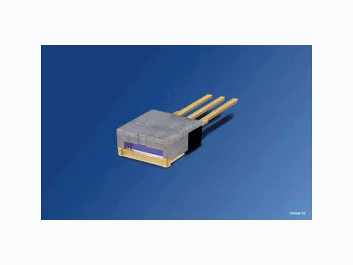
SPLLG81 OSRAM
Document overview
- Manufacturer or author: Provided By www.digicamel.com(FREE DATASHEET DOWNLOAD SITE)
- PDF pages: 8
Technical content
Features
Efficient radiation source for cw and pulsed operation Reliable InGa(Al)As strained quantum-well material Mounting of laser bar on expansion matched submount Compact package protecting the laser bar Integrated micro-cooler for efficient liquid cooling Window with emitting area of 7.0 mm x 0.3 mm Reduced fast axis divergence by use of internal lens
Applications
Pumping solid state lasers (rod, fiber and disk lasers) Direct material processing Medical applications Heating, Illumination Printing applications Safety Advices Depending on the mode of operation, these devices emit highly concentrated non visible infrared light which can be hazardous to the human eye. Products which incorporate these devices have to follow the safety precautions given in IEC 60825-1 “Safety of laser products”.
Wellenlänge1) Wavelength1) Bestellnummer Ordering Code SPL LG81 808 nm Q65110A2008 1) Andere Wellenlängen sind auf Anfrage erhältlich. Other wavelengths are available on request. Grenzwerte (20 ° C coolant temperature) Maximum Ratings Parameter Parameter Symbol Symbol Werte Values Einheit Unit min. max. Ausgangsleistung Output power Popt – 35 W Spitzen-Ausgangsleistung (quasi-continous wave, tp ≤ 200 µs, duty cycle ≤ 20%) Peak output power(quasi-continous wave, tp ≤ 200 µs, duty cycle ≤ 20%) Pqcw – 50 W Betriebstemperatur1) Operating temperature1) Top + 10 + 30 ° C Lagertemperatur1) Storage temperature1) 1) Betauung des Moduls muss ausgeschlossen werden. Bedewing of the module has to be excluded. Tstg - 40 + 85 ° C Löttemperatur (tmax = 10 s) Soldering temperature (tmax = 10 s) Ts – + 260 ° C
Dioden Kennwerte (20 ° C coolant temperature) Diode Characteristics Parameter Parameter Symbol Symbol Werte Values Einheit Unit min. typ. max. Zentrale Emissionswellenlänge1) 2) Emission wavelength1) 2) λpeak 805 808 811 nm Spektrale Breite (Halbwertsbreite)1) 2) Spectral width (FWHM)1) 2) ∆λ – 3.0 – nm Ausgangsleistung im Betriebspunkt1) Output power at operating point1) Pop – 30 – W Differentielle Effizienz Differential efficiency ηd 1.00 1.15 – W/A Schwellstrom Threshold current Ith 7 9 11 A Betriebsstrom1) Operating current1) Iop – 34 39 A Betriebsspannung1) 3) Operating voltage1) 3) Vop – 1.8 – V Differentieller Serienwiderstand Differential series resistance Rs – 7 – mΩ Konversionseffizienz (elektrisch zu optisch)1) Conversion efficiency (electrical to optical)1) ηcon – 0.49 – Charakteristische Temperatur (Schwelle)4) Characteristic temperature (threshold)4) T0 – 150 – K Temperaturkoeffizient des Betriebsstroms Temperature coefficient of operating current ∂Iop / Iop∂T – 0.5 – %/K Temperaturkoeffizient der Wellenlänge Temperature coefficient of wavelength ∂λ/∂T – 0.3 – nm/K Thermischer Widerstand (pn-Übergang → Kühlwasser) Thermal resistance (junction → coolant) Rth JA – 0.6 – K/W Kühlwassertemperatur5) 6) Coolant temperature5) 6) Tfluid + 10 + 20 + 30 °C Kühlwasserfluss5) 6) Coolant flow5) 6) Druckabfall (am Bauteil)6) Pressure drop (at device)6) ∆P 0.12 0.25 0.7 bar
Strahldivergenz fast-axis (Vollwinkel 1/e2) Beam divergence fast axis (full angle, 1/e2) θ⊥ 0.5 0.8 1.1 Grad deg. Strahldivergenz slow-axis (Vollwinkel 1/e2) Beam divergence slow axis (full angle, 1/e2) θ|| 4 6 8 Grad deg. Schielwinkel fast-axis Tilt angle fast axis ϕ⊥ -0.3 0 0.3 Grad deg. Schielwinkel slow-axis Tilt angle slow-axis ϕ|| -0.4 0 0.4 Grad deg. Strahlabmessungen am optischen Austritt Beam dimensions at optical output w × h – 7.0 × 0.4 – mm2 TE Polarisation TE Polarization PTE – 90 – % 1) Werte beziehen sich auf die Standardbetriebsbedingung 30 W Ausgangsleistung, 20 °C Kühlwassertemperatur und 0.6 l/min Kühlwasserfluss. Values refer to standard operating conditions of 30 W output power, 20 °C coolant temperature and 0.6 l/min coolant flow. 2) Die zentrale Emissionswellenlänge muss beim spezifizierten Strom kontrolliert werden. Liegt die Wellenlänge höher als im Testprotokoll spezifiziert, so weist dies auf einen schlechten ther mischen Kontakt und eine thermische Überbelastung der Laserdiode hin. Bevor der Laserbetri eb weitergeführt wird, mu ss der thermische Kontakt verbessert werden. Die zentrale Emissionswellenlänge schiebt mit 0,3 nm/K. Check the emission wavelength at the specified current. A much longer wavelength than specified in the test protocol indicates bad thermal contact and thermal overload of the diode laser. Then the thermal contact has to be improved before continuing laser operation. The emission wavelength shifts with 0.3 nm/K. 3) Das Anlegen einer Spannung in Sperrrichtung muss ausgeschlossen werden. Reverse voltage has to be excluded. 4) Modell zur Bestimmung des thermischen Verhaltens bzgl. des Schwellstroms: Model for the thermal behavior of threshold current: Ith(T2) = Ith(T1) × exp (T2 – T1)/T0 5) Temperatur und Fluss des Kühlwassers beeinflussen die Ausgangsleistung, die zentrale Emissionswellenlänge und die Lebensdauer. Betauung muss ausgeschlossen werden. Coolant temperature and flow influences output power, em ission wavelength and lifetime. Condensation has to be excluded. 6) Als Kühlwasser muss vollständig entionisiertes (VE-) Wasser verwendet werden mit einer maximalen Partikelgröße von 5 µm und einem maximalen Leitwert von 4 µS/cm. As coolant de-ionized (DI-) water has to be used with a maximum particle size of 5 µm and a maximum conductivity of 4 µS/cm. Dioden Kennwerte (20 ° C coolant temperature) Diode Characteristics (cont’d) Parameter Parameter Symbol Symbol Werte Values Einheit Unit min. typ. max.
Ligth-current and voltage-current curves (cw, 20 °C, 0.6 l/min) Pressure drop at device vs. coolant flow (30 W cw, 20°C) Optical spectrum, relative intensity Irel vs. wavelength λ (30 W cw, 20 ° C, 0.6 l/min) Emission wavelength vs. coolant flow (30 W cw, 20 °C) OHW02503 V A V I 0.5 1.0 1.5 2.0 10 20 30 40 W OUTP Voltage Output Power bar OHW02500 Coolant Flow l/min0.2 0.4 0.6 1 0.1 0.2 0.3 0.4 0.5 0.6 0.7Pressure Drop 800 nm OHW02504 100 Irel λ 805 810 815 807 nm OHW02501 808 809 810 811 812 Coolant Flow λ l/min0.2 0.4 0.6 1
Laser current vs. coolant flow (30 W cw, 20 °C) 33.0 A OHW02502 Coolant Flow l/min0.2 0.4 0.6 1 I 33.4 33.8 34.6 @ 30 W
Maßzeichnung Package Outlines Maße in mm (inch) / Dimensions in mm (inch). Allgemeine Toleranz: +/- 0.15 mm (0.006 inch) / General Tolerance: +/- 0.15 mm (0.006 inch) Notes: Der optische Strahlaustritt liegt 1.5 mm über der Unterseite der Gehäusegrundplatte. Exit height of optical output beam is 1.5 mm referring to bottom side of package base plate. Gehäusegrundplatte ist auf Anodenpotential. Package base plate is on anode potential. 8.5 (0.335) 10.14 (0.399) 2.54 (0.100) 1.05 (0.041) 2.54 (0.100) 10 (0.394) 0.75 (0.030) 4.7 (0.185) 7.7 (0.303) GTOY6607 2.4 (0.094) 1.5 (0.059) 1.3 (0.051) Port Output Optical 1.3 (0.051) 0.5 (0.020) 4.45 (0.175) +0.10 (0.003) -0.1 (0.003)
OSRAM Opto Semiconductors GmbH Wernerwerkstrasse 2, D-93049 Regensburg www.osram-os.com © All Rights Reserved. The information describes the type of component and shall not be considered as assured characteristics. Terms of delivery and rights to change design reserv ed. Due to technical requirements components may contain dangerous substances. For information on the types in question please contact our Sales Organization. Packing Please use the recycling operators known to you. We can also help you – get in touch with your nearest sales office. By agreement we will take packing material back, if it is sorted. You must bear the costs of tr ansport. For packing material that is returned to us unsorted or which we are not obliged to accept, we shall have to invoice you for any costs incurred. Components used in life-support devices or system s must be expressly authorized for such purpose! Critical components 1 , may only be used in life-support devices or systems 2 with the express written approval of OSRAM OS. 1 A critical component is a component usedin a life-support device or system whose failure can reasonably be expected to cause the failure of that life-support device or system, or to affect its safety or effectiveness of that device or system. 2 Life support devices or systems are intended (a) to be implanted in the human body, or (b) to support and/or maintain and sustain human life. If they fail, it is reasonable to assume that the health of the user may be endangered.