
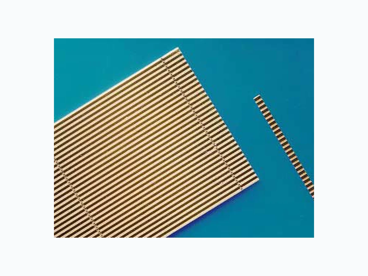
SPLBS94-2S OSRAM
Document overview
- Manufacturer or author: Provided By www.digicamel.com(FREE DATASHEET DOWNLOAD SITE)
- PDF pages: 4
Technical content
Features
Un-mounted monolithic linear array 75 emitter (82.5% fill-factor) design Recommended optical power 200 W Typical conversion efficiency 54 % High efficiency and re liable MOVPE-grown quantum-well structure Standard wavelength selection is ± 3n m Other pulse peak wavelengths are available upon request Solderable p- and n-side metallization Al-free active region
Applications
Recommended for quasi continuous wave (qcw)- applications Pumping of solid state lasers Direct material processing Heating, illumination Medical applications Printing applications Safety Advices Depending on the mode of operation, these devices emit highly concentrated non-visible infrared light which can be hazardous to the human eye. Products which incorporate these devices have to follow the safety precautions found in IEC 60825-1 “Safety of laser products”.
Leistung1) Power1) Wellenlänge2) Wavelength2) Bestellnummer Ordering Code SPL BS94-2S 200 W 932 nm Q65110A6958 1) Empfohlene Leistung setzt einen geringen thermischen Widerstand von Rth < 0.5 K/W voraus. Recommended optical power implies a low thermal resistanceof Rth < 0.5 K/W. 2) Mittlere Wellenlänge bei 1 μs Pulsbreite und 4 kHz Wiederholfrequenz eines unmontierten Barren. Andere Wellenlängen oder Toleranzen auf Anfrage erhältlich. Pulsed peak wavelength at 1 μs pulse width and at 4 kHz repetition rate refer to measurement on an un-mounted laser bar. Other peak wavelengths or tolerances are available upon request. Kennwerte (TA = 25 °C)1) Characteristics1) Bezeichnung Parameter Symbol Symbol Wert Values Einheit Unit min. typ. max. Empfohlene Ausgangsleistung Recommended output power Pop -2 0 0 QCW Zerstörgrenze Catastrophic optical damage limit PCOD 350 500 - W Schwellstrom Threshold current Ith -1 5 1 8 A Betriebsstrom2) Operatiing current 2) Iop - 198 218 A Differentielle Quanten-Effizienz2) Differential quantum efficiency2) η 1.0 1.1 - W / A Gesamter Konversionswirkungsgrad2) Total conversion efficiency2) η tot 51 54 - % Strahldivergenz schnelle Achse Vollwinkel (1/e²)2) Beam divergence fast-axis2) full width (1/e²) θ⊥ -6 5 7 0 G r a d deg. Strahldivergenz langsame Achse2) Vollwinkel (1/e²) Beam divergence slow-axis2) full width (1/e²) θII - 9 12 Grad deg. Zentrale Impulswellenlänge2) Standard pulse center wavelength2) λpulse 927 932 937 nm
Spektrale Breite (Halbwertsbreite)2) Spectral width (FWHM)2) Δλ -3 5 n m TE Polarisation 2) TE Polarization 2) PTE -9 0 -% 1) Alle Kenn- und Grenzwerte beziehen sich auf Impulsmessungen (1 μs Pulsbreite bei 4 kHz Wiederholfrequenz) an unmontierten Barren. Die Erzielung der spezifizierten Werte im QCW – Modus (Quasi Continuous Wave) setzt eine geeignete Montagetechnik mit ei nem thermischen Widerstand von Rth< 0.5 K/W voraus. Die zentrale Emissionswellenlänge im Betrieb ist abhängig vom Betri ebsmodus, Betriebstemperatur, thermischer Widerstand Rth und ist in aller Regel höher als die spezifizierte Impulswellenlänge λpulse (1 μs Pulsbreite bei 4 kHz Wiederholfrequenz). Alle Parameter können im jeweili gen Betriebsmodus von den spezifizierten Kennwerten abweichen. All characteristics and limitations refer to pulsed measurements (1 μs pulse width at 4 kHz repetition Wave) implies a suitable mounting technology with a thermal resistance of Rth< 0.5 K/W. The operating peak emission wavelength depends on the operating mode, ambien t temperature and thermal resistance Rth. The operating peak emission wavelength in general is higher than the specified pulsed peak wavelength λpulse (1 μs pulse width at 4 kHz repetition rate). All characteristics obtained in the operating mode may differ from the characteristics specified herein. 2) Spezifiziert bei der typischen optischen Ausgangsleistung Pop, typ Specified at the typical, optical output power Pop, typ Kennwerte (TA = 25 °C)1) Characteristics1) Bezeichnung Parameter Symbol Symbol Wert Values Einheit Unit min. typ. max.
OSRAM Opto Semiconductors GmbH Wernerwerkstrasse 2, D-93049 Regensburg www.osram-os.com © All Rights Reserved. The information describes the type of component and shall not be considered as assured characteristics. Terms of delivery and rights to change design reserv ed. Due to technical requirements components may contain dangerous substances. For information on the types in question please contact our Sales Organization. Packing Please use the recycling operators known to you. We can also help you – get in touch with your nearest sales office. By agreement we will take packing material back, if it is sorted. Y ou must bear the costs of transport. For packing material that is returned to us unsorted or which we are not obliged to accept, we shall have to invoice you for any costs incurred. Components used in life-support devices or system s must be expressly authorized for such purpose! Critical components 1 , may only be used in life-support devices or systems 2 with the express written approval of OSRAM OS. 1 A critical component is a component usedin a life-support device or system whose failure can reasonably be expected to cause the failure of that life-support device or system, or to affect its safety or effectiveness of that device or system. 2 Life support devices or systems are intended (a) to be implanted in the human body, or (b) to support and/or maintain and sustain human life. If they fail, it is reasonable to assume that the health of the user may be endangered. Dimensionen Dimensions Bezeichnung Parameter Symbol Symbol Werte Values Einheit Unit min. typ. max. Emitteranzahl Number of emitters n -7 5- Kontaktbreite je Emitter Single emitter contact width w - 110 - μm Emitterabstand Emitter pitch p - 130 - μm Packungsdichte Fill-factor F -8 2 . 5- % Barrenbreite Bar width W 9.9 10 10.1 mm Barrenhöhe Bar height H 105 115 125 μm Resonatorlänge Resonator length L 1190 1200 1210 μm