
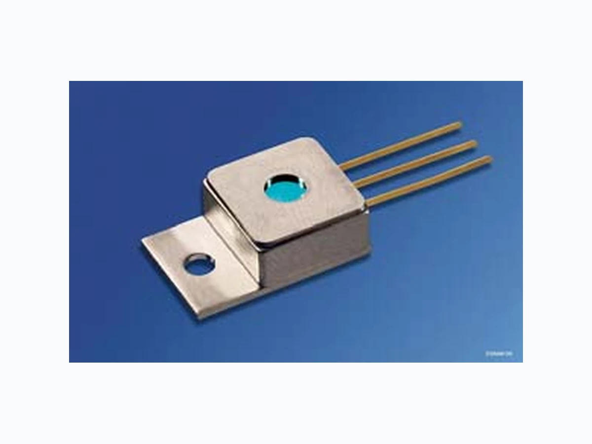
SPL2Y94-2S OSRAM
Document overview
- Manufacturer or author: Provided By www.digicamel.com(FREE DATASHEET DOWNLOAD SITE)
- PDF pages: 7
Technical content
Features
Efficient radiation source for cw and pulsed operation Reliable InGa(Al)As strained layer quantum-well structure New optimized single quantum-well structure Improved reliability, low treshold current, higher efficiency Small TO-220 package with efficient thermal coupling Included thermistor allows wavelength control by temperature Laser aperture 200 µm Cylindrical lens for correction of the vertical axis
Applications
Pumping of solid state lasers (Nd: YAG, Yb: YAG, …) Medical and dental applications Soldering, heating, illumination Free space data transmission Energy transmission Testing and measuring applications Safety Advices Depending on the mode of operation, these devices emit highly concentrated non visible infrared light which can be hazardous to the human eye. Products which incorporate these devices have to follow the safety precautions given in IEC 60825-1 “Safety of laser products”.
Wellenlänge Wavelength1) Bestellnummer Ordering Code SPL 2Y94-2S 940 nm Q65110A1830 1) Andere Wellenlängen im Bereich von 780 nm … 980 nm sind auf Anfrage erhältlich. Other wavelengths in the range of 780 nm … 980 nm are available on request. Grenzwerte (kurzzeitiger Betrieb) (TA = 25 °C) Maximum Ratings (short time operation) Bezeichnung Parameter Symbol Symbol Wert Values Einheit Unit min. max. Ausgangsleistung (Dauerstrichbetrieb)1)2) Output power (continuous wave)1)2) 1) Der Betrieb bei den Grenzwerten beeinflusst die Lebensdauer. The operation at the maximum ratings influences the life time. 2) Zur Leistungsmessung wird die gesamte Lichtleistung in eine Ulbrichtkugel eingekoppelt. Optical power is measured by coupling into an integrating sphere. Pcw – 3.0 W Ausgangsleistung (Quasi-Dauerstrichbetrieb)1)2) (tp ≤ 150 µs, Tastverhältnis ≤ 30%) Output power (quasi-continuous wave)1)2) (tp ≤ 150 µs, duty cycle ≤ 30%) Pqcw – 4.0 W Sperrspannung Reverse voltage VR – 3 V Betriebstemperatur3) Operating temperature3) 3) Die Entstehung von Kondensflüssigkeiten muß ausgeschlossen werden. Bedewing has to be excluded. Top – 10 + 60 °C Lagertemperatur3) Storage temperature3) Tstg – 40 + 85 °C Löttemperatur an den Anschlüssen, max. 10 s Soldering temperature at the pins, max. 10 s Ts – 260 °C
Diodenkennwerte (TA = 25 °C) Diode Characteristics Bezeichnung Parameter Symbol Symbol Wert Values Einheit Unit min. typ. max. Zentrale Emissionswellenlänge1) Emission wavelength1) λpeak 930 940 950 nm Spektrale Breite (Halbwertsbreite)1) Spectral width (FWHM)1) ∆λ – 3.00 – nm Opt. Ausgangsleistung im Betriebspunkt2) Output power2) Pop – 2.00 – W Differentielle Effizienz Differential efficiency η 0.80 1.00 – W/A Schwellstrom Threshold current Ith 0.35 0.45 0.60 A Betriebsstrom1)2) Operating current1)2) Iop – 2.50 3.00 A Betriebsspannung1)2) Operating voltage1)2) Vop – 1.90 2.10 V Differentieller Serienwiderstand Differential series resistance Rs – 0.15 0.25 Ω Strahldivergenz (Halbwertsbreite) Beam divergence (FWHM) deg. Strahldivergenz (1/e²) Beam divergence (1/e²) deg. Charakteristische Temperatur (Schwelle)3) Characteristic temperature (threshold)3) T0 – 220 – K Temperaturkoeffizient des Betriebsstroms Temperature coefficient of operating current ∂Iop/Iop∂T – 0.50 – %/K Temperaturkoeffizient der Wellenlänge Temperature coefficient of wavelength ∂λ/∂T – 0.30 – nm/K
RT = R0 × exp (B × (1/T – 1/T0)) R0 = 10 kΩ ± 3%, T0 = 25 °C = 298 K, B = 3730 K Thermischer Widerstand (pn-Übergang → Wärmesenke) Thermal resistance (junction → heat sink) Rth JA – 5 – K/W 1) Standardbetriebsbedingungen beziehen sich auf 2 W cw optische Ausgangsleistung. Standard operating conditions refer to 2 W cw optical output power. 2) Optische Leistungen werden mit einer Ulbrichtkugel gemessen. Optical power measurements refer to an integrating sphere. 3) Modelle zur Bestimmung des thermischen Verhaltens bzgl. des Schwellstroms: Ith(T2) = Ith(T1) × exp (T2 – T1)/T0 Model for the thermal behavior of threshold current: Ith(T2) = Ith(T1) × exp (T2 – T1)/T0 Diodenkennwerte (TA = 25 °C) Diode Characteristics (cont’d) Bezeichnung Parameter Symbol Symbol Wert Values Einheit Unit min. typ. max. OHL01668 NTCR T 350 250 200 100 150 kΩ -40 -20 0 20 60 40 ˚C 100
Optical Output Power Popt vs. Forward Current IF (TA = 25 °C) SPL 2Y94-2S Farfield Distribution Parallel to Junction Ιrel vs. θ||, typical curve Optical Characteristics Optical Spectrum, Relative Intensity Ιrel vs. Wavelength λ (TA = 25 °C, Popt = 2.0 W) SPL 2Y94-2S Farfield Distribution Perpendicular to Junction Ιrel vs. θ⊥, typical curve OHL01664 optP FI 0.5 1.0 1.5 2.0 2.5 W 1 2 A 30.5 1.5 2.5 OHW01384 relΙ -10 0.5 1.0 -5 0 5 10deg. Θ OHW00798 0920 λ 930 940 950 960nm 0.25 0.5 0.75 Ιrel Θ OHW01395 relΙ -5 deg.0 5 0.5 1.0
Alle Laser werden vorgetestet und gemäß den gemessenen Kennwerten ausgeliefert. Bezüglich Sicherheit, Verpackung, Behandlung, Montage und Betriebsbedingungen lesen Sie bitte sorgfältig unsere „Notes for Operation I“. Mechanische Montage Befestigungsloch (geeignet für M 2.5). Durch die gute Wäremeleitfähigkeit der TO-220 Bodenplatte (Kupfer) wird die Wärme auch bei Befestigung an nur einer Seite gut abgeleitet. Zur exakten Positionierung des Gehäuses und anderer Teile, z.B. Linsen, kann das TO-220-Gehäuse mit entsprechenden Klemmen oder Schrauben (max. M 2.5) befestigt werden. All devices are pretested and will be delivered including measured laser characteristics. For safety, unpacking, handling, mounting, and operating issues, please read carefully our “Notes for Operation I”. Mechanical Attachment Mounting hole (suitable for M 2.5) Because of the good thermal conductivity of the TO 220 base plate (copper) the heat loss is properly dissipated even if the component is attached on one side only. For exact positioning of the TO component and other parts, e.g. lenses, the TO 220 package can be attached with appropriate clamping devices or screws (max. M 2.5).
Maßzeichnung Package Outline Maße in mm (inch) / Dimensions in mm (inch). Published by OSRAM Opto Semiconductors GmbH Wernerwerkstrasse 2, D-93049 Regensburg www.osram-os.com © All Rights Reserved. The information describes the type of component and shall not be considered as assured characteristics. Terms of delivery and rights to change design reserv ed. Due to technical requirements components may contain dangerous substances. For information on the types in question please contact our Sales Organization. Packing Please use the recycling operators known to you. We can also help you – get in touch with your nearest sales office. By agreement we will take packing material back, if it is sorted. You must bear the cost s of transport. For packing material that is returned to us unsorted or which we are not obliged to accept, we shall have to invoice you for any costs incurred. Components used in life-support devices or system s must be expressly authorized for such purpose! Critical components 1 , may only be used in life-support devices or systems 2 with the express written approval of OSRAM OS. 1 A critical component is a component usedin a life-support device or system whose failure can reasonably be expected to cause the failure of that life-support device or system, or to affect its safety or effectiveness of that device or system. 2 Life support devices or systems are intended (a) to be implanted in the human body, or (b) to support and/or maintain and sustain human life. If they fail, it is reasonable to assume that the health of the user may be endangered. GTOY6063 10.8 (0.425) 10.4 (0.409) 2.75 (0.108) 2.45 (0.096) 3.2 (0.126) 2.8 (0.110) 10.8 (0.425) 10.4 (0.409) 2.74 (0.108) 2.34 (0.092) 2.74 (0.108) 2.34 (0.092) 1.0 (0.039) 0.6 (0.024) 3.0 (0.118) 2.6 (0.102)
1 Cathode
2 NTC
3 NTC
ø0.5 (0.020) ø0.7 (0.028) 123 5.5 (0.216) 4.9 (0.192)