
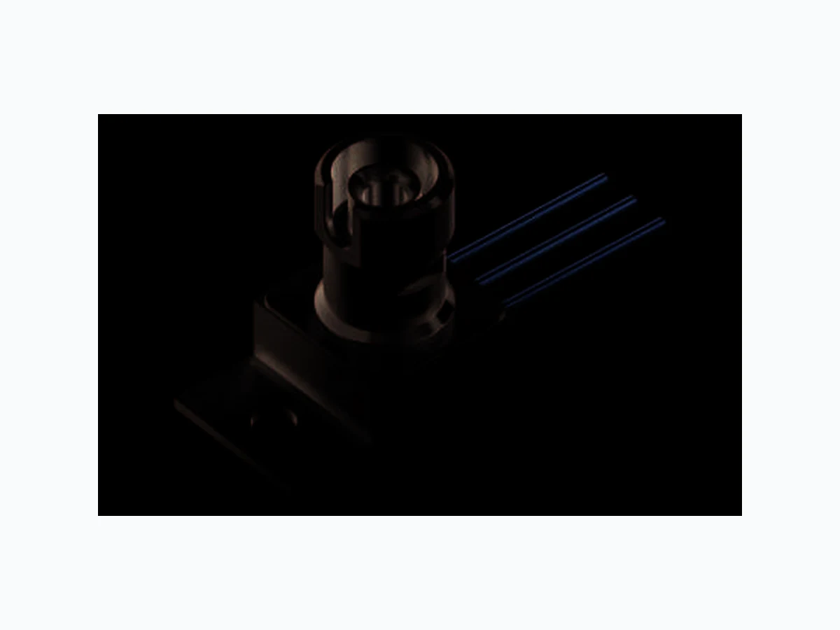
SPL-2F81-2S OSRAM
Document overview
- Manufacturer or author: Provided By www.digicamel.com(FREE DATASHEET DOWNLOAD SITE)
- PDF pages: 8
Technical content
Laser Diode in TO-220 Package with FC-Connector 1.5 W cw Version 1.1 SPL 2F81-2S
Ordering Information
Features: Efficient radiation source for cw and pulsed operat ion
- Reliable InGa(Al)As strained quantum-well structure
- New optimized single quantum-well structure
- Improved reliability, low treshold current, higher efficiency
- Small TO-220 package with efficient thermal couplin g
- Included thermistor allows wavelength control by te mperature
- FC-type connector for efficient fiber coupling into a 200 µm / 0.22 NA fiber
Applications
Pumping of fiber lasers and amplifiers (Er,Yb)
- Pumping of solid state lasers (Nd: YAG, Yb: YAG)
- Medical applications
- Soldering, heating, illumination
- Energy transmission
- Testing and measuring applications Notes Depending on the mode of operation, these devices e mit highly concentrated non visible infrared light which can be hazardous to the human eye. Products which i ncorporate these devices have to follow the safety precautions given in IEC 60825-1 "Safety of laser p roducts". Type: Peak wavelength 1) page 7 Ordering Code λpeak [nm] SPL 2F81-2S 808 Q65110A1722
Version 1.1 SPL 2F81-2S Maximum Ratings (TA = 25 °C) Characteristics (TA = 25 °C) Parameter Symbol Values Unit Output power (continuous wave) 2) page 7 , 3) page 7 Pcw 2 W Output power (quasi-continuous wave) 2) page 7 , 3) page 7 (tp ≤ 150 µs, duty cycle ≤ 30 %) Pqcw 3 W Reverse voltage VR 3 V Operating temperature 4) page 7 Top -10 ... 60 °C Storage temperature range 4) page 7 Tstg -40 ... 85 °C Soldering temperature at the pins, max. 10 s T s1 260 °C Parameter Symbol Values Unit min typ max Emission wavelength 5) page 7 λpeak 805 808 811 nm Spectral width (FWHM) 5) page 7 ∆λ 3 nm Peak output power 6) page 7 , 7) page 7 Popt 1.5 W Differential efficiency 6) page 7 , 7) page 7 η 0.65 0.8 W / A Threshold current Ith 0.5 0.6 0.7 A Operating current 5) page 7 , 6) page 7 , 7) page 7 Iop 2.5 3 A Operating voltage 5) page 7 Vop 2 2.2 V Differential series resistance Rs 0.15 0.25 Ω Fiber diameter D 50 200 µm Numerical aperture NA 0.22 Characteristic temperature (threshold) 8) page 7 T0 1 1.5 2 K Temperature coefficient of operating current ∂I op / Iop ∂T 0.5 % / K Temperature coefficient of wavelength ∆λ / ∆T 0.3 nm / K Thermal resistance (junction → heat sink) R th 5 K / W
Version 1.1 SPL 2F81-2S 2016-03-02 3 Typical Coupling Efficiency by Using Other Fiber Ty pes (Standard fiber: core Ø 200 µm, 0.22 NA, η c = 1) Optical power from the fiber output with the coupli ng efficiency η c Popt = η x η c x (I - I th ) Core Diameter Ø (µm) Numerical Aperture NA Coupling Efficiency η c(W/A) 125 0.35 0.95 100 0.22 0.85 50 0.22 0.35 Opt. Output Power vs. Forward Current TA = 25 °C Relative Spectral Emission TA = 25 °C, P opt = 1.5 W OHW01396 IF optP 1 2 3A W 0.2 0.4 0.6 0.8 1.0 1.2 1.4 1.6 1.8 OHW01397 790 nm λ relΙ 800 810 820 830 0.25 0.50 0.75 1.00
Version 1.1 SPL 2F81-2S NTC Thermistor RT = R 0 x exp (B x (1/T - 1/T 0)) R0 = 10 kΩ ± 3%, T 0 = 25 °C = 298 K, B = 3730 K Notes for Operation I All devices are pre-tested and will be delivered in cluding measured laser characteristics. For safety, unpacking, handling, mounting, and operating issues , please read carefully our "Notes for Operation I" . Mechanical Attachment Mounting hole (suitable for M 2.5). Because of the good thermal conductivity of the TO 220 base plate (copper) the heat loss is properly dissipated even if the component is attached on one side only. For exact positioning of the TO component and other parts, e. g. lenses, the TO 220 package can be attached with appropriate clampig devices or screws (max. M 2.5). OHL01668 NTCR T 350 250 200 100 150 kΩ -40 -20 0 20 60 40 ˚C 100
Version 1.1 SPL 2F81-2S 2016-03-02 5 Package Outline Dimensions in mm (inch). GTOY6062 2.75 (0.108) 2.45 (0.096) 10.8 (0.425) 10.4 (0.409) 3.2 (0.126) 2.8 (0.110) 10.8 (0.425) 10.4 (0.409) 16.7 (0.657) 16.3 (0.642) 12.4 (0.488) 14.0 (0.551) 1 2 3 2.74 (0.108) 2.34 (0.092) 2.74 (0.108) 2.34 (0.092) 1.0 (0.039) 0.6 (0.024) 1.2 (0.047) 1.0 (0.039) 14.3 (0.563) 13.5 (0.531) SW 5.5 2.5 (0.098) 2.3 (0.091) M8 × 0.75 2.5 (0.098) 2.2 (0.087) 4.6 (0.181) 4.4 (0.173) 8.5 (0.335) 8.7 (0.343 ø0.7 (0.028) 3.0 (0.118) 5.2 (0.205) 5.0 (0.197)
3 NTC
2 NTC
1 Cathode
5.5 (0.216) 4.9 (0.192)
Version 1.1 SPL 2F81-2S TTW Soldering IEC-61760-1 TTW Disclaimer Language english will prevail in case of any discre pancies or deviations between the two language word ings. Attention please! The information describes the type of component and shall not be considered as assured characteristics . Terms of delivery and rights to change design reser ved. Due to technical requirements components may c ontain dangerous substances. For information on the types in question please con tact our Sales Organization. If printed or downloaded, please find the latest ve rsion in the Internet. Packing Please use the recycling operators known to you. We can also help you – get in touch with your nearest sales office. By agreement we will take packing material back, if it is sorted. You must bear the costs of transport . For packing material that is returned to us unsorted or which w e are not obliged to accept, we shall have to invoi ce you for any costs incurred. Components used in life-support devices or systems must be expressly authorized for such purpose! Critical components* may only be used in life-suppo rt devices** or systems with the express written ap proval of OSRAM OS. *) A critical component is a component used in a li fe-support device or system whose failure can reaso nably be expected to cause the failure of that life-support device or system, or to affect its safety or the ef fectiveness of that device or system. **) Life support devices or systems are intended (a ) to be implanted in the human body, or (b) to supp ort and/or maintain and sustain human life. If they fail, it i s reasonable to assume that the health and the life of the user may be endangered. 00 s OHA04645 100 150 200 250 300 t T 235 ˚C - 260 ˚C First wave 20 40 60 80 100 120 140 160 180 200 220 240 Second wave 10 s max., max. contact time 5 s per wave Preheating 100 ˚C 120 ˚C 130 ˚C Typical Cooling ca. 3.5 K/s typical ca. 2 K/s ca. 5 K/s Continuous line: typical process Dotted line: process limits < 150 K
Version 1.1 SPL 2F81-2S 2016-03-02 7 Glossary 1) Wavelength: Other wavelengths in the range of 780 nm ... 980 nm are available on request. 2) Output power: The operation at the maximum ratings influences the life time. 3) Output power: Optical data refer to the output from a fiber stub (core Ø 200 µm, 0.22 NA). 4) Operating and storage temperature: Bedewing has to be excluded. 5) Standard operating conditions: Standard operating conditions refer to 1.5 W cw opt ical output power. 6) Standard operating conditions: Standard operating conditions refer to the usage of a multimode fiber (core Ø 200 µm, 0.22 NA) 7) Output power: Optical power is measured by coupling into an integ rating sphere. 8) Characteristic temperature (threshold): Model for the thermal behavior of threshold current : Ith (T 2) = I th (T 1) x exp (T 2 -T 1)/T 0
Version 1.1 SPL 2F81-2S Published by OSRAM Opto Semiconductors GmbH Leibnizstraße 4, D-93055 Regensburg www.osram-os.com © All Rights Reserved.