
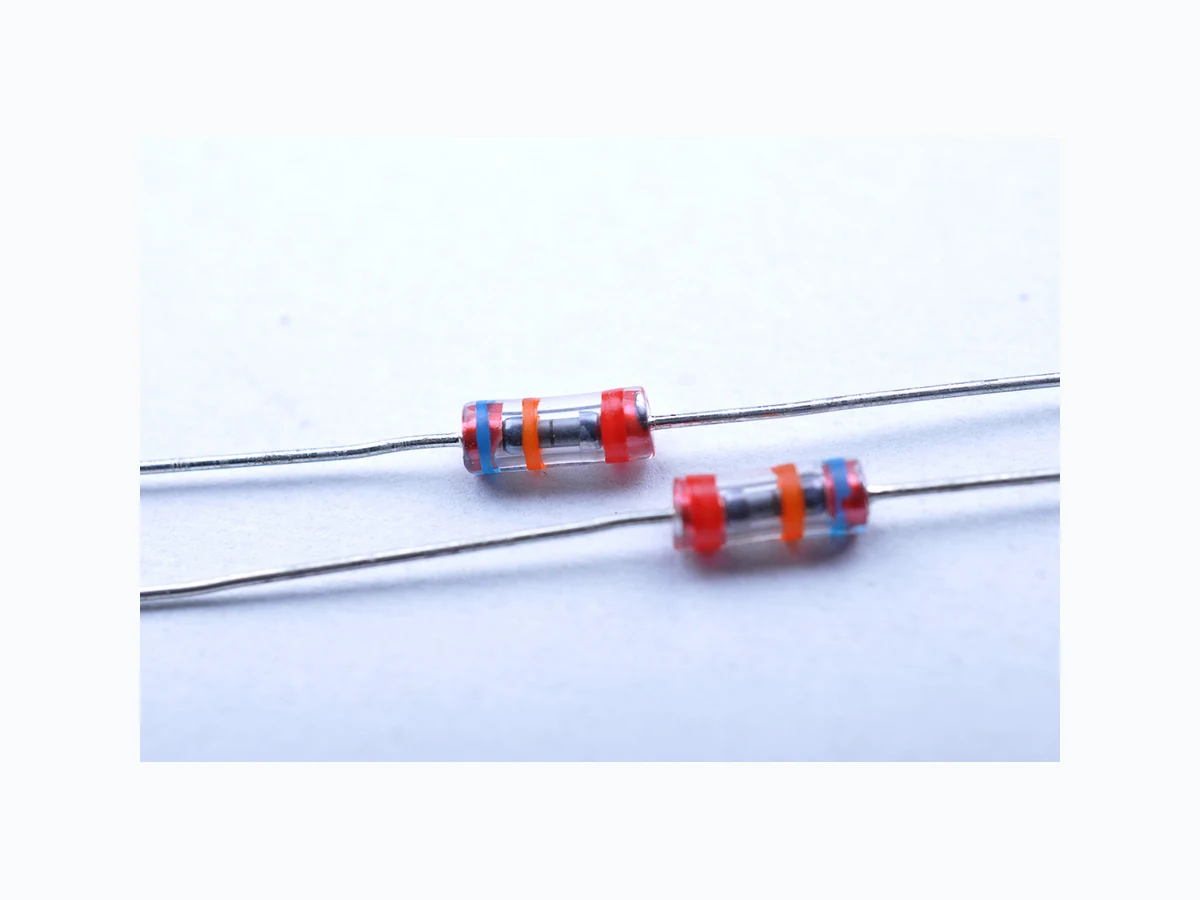
SPG32-501 LEIDITECH
Document overview
- Manufacturer or author: Provided By www.digicamel.com(FREE DATASHEET DOWNLOAD SITE)
- PDF pages: 5
Technical content
Features
- Power Supplies
- Motor sparks eliminating
- Relay switching spark absorbing
- Data line pulse guarding
- Telephone/Fax/Modem
- High frequency signal transmitters/receivers
- Satellite antenna
- Radio amplifiers
- Alarm systems
- Cathode ray tubes in Monitors/TVs 28±2.0 0.5±0.05 Φ3.1±0.5 6.7±1.0 28±2.0 Rev : www.leiditech.com 01.06.2017 1/5 SPG32-501 Series
ElectrIcal CharacterlstIcs Type Number DC Spark-Over Voltage Minimum Insulation Resistance Maximum Capacitance (1kHz-6Vmax ) Surge Current Capacity Surge Life Test 10x700µsVs R Test Voltage CJ 8/20µs V MΩ V pF A 140±30% 100 50 1 3000 6000V 10 times 200±20% 100 50 1 3000 6000V 10 times 300±20% 100 100 1 3000 6000V 10 times 400±20% 100 250 1 3000 6000V 10 times 500±20% 100 250 1 3000 6000V 10 times 600±20% 100 250 1 3000 6000V 10 times 1000±20% 100 500 1 3000 6000V 10 times 1200±20% 100 500 1 3000 6000V 10 times 1500±20% 100 500 1 3000 6000V 10 times 1800±20% 500 500 1 3000 6000V 10 times 2000±20% 500 500 1 3000 6000V 10 times 2400±20% 500 500 1 3000 6000V 10 times 3000±20% 500 500 1 3000 6000V 10 times 3600±20% 500 500 1 3000 6000V 10 times 4500±20% 500 500 1 3000 6000V 10 times Rev : www.leiditech.com 01.06.2017 2/5 SPG32-141 SPG32-201 SPG32-301 SPG32-401 SPG32-501 SPG32-601 SPG32-102 SPG32-122 SPG32-152 SPG32-182 SPG32-202 SPG32-242 SPG32-302 SPG32-362 SPG32-452
M z di/dt Test Methods And Results Items Test Method Standard DC Spark-over Voltage Measure starting discharge voltage (Vs) by gradually increasing applied DC voltage. Test current is 0.5mA max. And the DC voltage ascends up within 100V/s(Vs<1000V) or 500V/ s(Vs≥1000V). Meet specified value. Insulation Resistance Measure the insulation resistance across the terminal at regular voltage. But the test voltage doesn’t over the DC spark-over voltage. Capacitance Measure the electrostatic capacitance by applying a voltage of less than 6V (at 1KHz) between terminals. Static Life 10KV with 1500pf condenser is discharged through 0Ω resistor. 200 times at an interval of 10sec. ∣△ Vs/Vs ∣ ≤30% Characteristics of other items must meet the specified value. Surge Current Capacity The following impulse current for specified current applied ±5 times, each time interval 60 seconds. Thereafter, outer appearance shall be visually examined. No crack and no failures Cold Resistance Measurement after -40℃ /1000 HRS & normal temperature/2 HRS. Features are conformed to rated spec. Heat Resistance Measurement after 125℃ /1000 HRS & normal temperature/2 HRS. Humidity Resistance Measurement after humidity 90~95 ℃ (45 ℃ ) /1000 HRS & normal temperature/2 HRS. Temperature Cycle 10 times repetition of cycle -40 ℃ /30min →normal, temp/2 min →125℃ /30min, measurement after normal temp/2 HRS. Solder Ability Apply flux and immerse in molten solder 230±5℃ for 3sec up to the point of 1.5mm from ℃ body. Check for solder adhesion. Lead wire is evenly covered by solder. Solder Heat Measurement after lead wire is dipped up to the point of 1.5mm from body into 260±5 ℃ solder for 10sec. Conformed to rated spec. Pull Strength Apply 0.5kg load for 10sec. Lead shall not pull out to snap. Flexural Strength Bend lead wire at the point of 2mm from body under 0.25 load and back to its original point.Repeat 1 time. Type Impulse current Vs < 400V 1.2/50μs & 8/20μs, 3000A Vs ≥ 400V 1.2/50μs & 8/20μs, 3000A, electrically connected with a resistor (1~2 Ω). Rev : www.leiditech.com 01.06.2017 3/5
Recommended Soldering Conditions Flow Solder i ng Co n d itio n s Reflow Sol d ering C o nditions T ime sh o w n in the a b ove figu r es is measured from the point when chip surf ace reac h e s temperature. T e mpera t ure di f f eren c e in high t empera t u r e par t should be wi t hin After soldering, do not force cool allow the parts to cool graduall y Hand Soldering Solder iron temperat u r 350±5 Heating time: s e conds max. General attention to soldering High soldering tempe r atures and long solderi n g times can cause leaching of the terminati on, decrease i n adh e ren c e s t reng t h and t he c hange o f characteristic may occu r For solder i ng, please r e fer to the s o lderi n g curves abo v e H o w e v e r ple a s e k eep ex p o sures to temperatu r es exceedi n g to fewer than seconds. Please use a mild flux (containing less than 0.2wt% CI). Also, if the flux is water soluble, be su r e to was h thoro u ghly t o remove a n y residue from the undersi d e of components that coul d a f fect resistance. Cle a nin g When using ultrasonic cl e aning, the b o ar d ma y re s o na t e i f t he o u t pu t power i s too high. Si n c e th is vibra t ion can cause cracking or a decrease in t he a dhe r en c e o f t he t e rm ina t ion, we recommend that y ou u s e t he c ondi t ion s bel o w Frequ e ncy: 40kHz max. Output pow e r 20W/liter Cleani n g time: minutes max. 60~120 sec 60~120 sec 150~180 150~180¥ 260 260¥ Soldering Cooling Air Priheat Soldering CoolingAir Priheat 3~4 sec 10 sec or less 60 sec or less 100 150 200 250 100 150 200 250 Flow Soldering Conditions 1) Time shown in the above figures is measured from the point when chip surface reaches temperature. 2) Temperature difference in high temperature part should be within 110℃ 3) After soldering, do not force cool, allow the parts to cool gradually. Hand Soldering Solder iron temperature: 350±5℃ Heating time: 3 seconds max. General attention to soldering
- High soldering temperatures and long soldering times can cause leaching of the termination, decrease in adherence strength, and the change of characteristic may occur.
- For soldering, please refer to the soldering curves above. However, please keep exposures to temperatures exceeding 200 ℃ to fewer than 50 seconds.
- Please use a mild flux (containing less than 0.2wt% CI). Also, if the flux is water soluble, be sure to wash thoroughly to remove any residue from the underside of components that could affect resistance. Cleaning When using ultrasonic cleaning, the board may resonate if the output power is too high. Since this vibration can cause cracking or a decrease in the adherence of the termination, we recommend that you use the conditions below. Frequency: 40kHz max. Output power: 20W/liter Cleaning time: 5 minutes max. Rev : www.leiditech.com 01.06.2017 4/5
Symbol Dimension (mm) W 52.0±2.0 P 5.0±0.5 L1-L2 1.0 max. T 6.0±1.0 Z 1.2max. t 3.2max. S 0.8max. D Φ3.6max D1 Φ0.5±0.05 L 7.7max A 75.0 B 68.0 C 255.0 Antity: 2000PCS
Ordering Information
Shanghai Leiditech Electronic Co.,Ltd Email: sale1@leiditech.com Tel : +86- 021 50828806 Fax : +86- 021 50477059 Rev : www.leiditech.com 01.06.2017 5/5