


 Download PDF
DATASHEET SEARCH SITE
Document overview
- PDF pages: 4
Technical content
Page 1
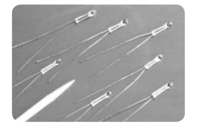
NTC Type
SP Series
Ultra-stable Probe
Thermistors
The NTC Type SP60, SP65, SP85, and SP100 Ultra-stable Probe Thermistors have similar construction and dimensions to the Type P60, P65, P85, and P100 Probe Thermistors. Ultra-stable Probe Thermistors receive additional processing to assure their continuous use in one of three temperature classes and are categorized into one of six stability groups.
Applications
The NTC Type SP60, SP65, SP85, and SP100 Ultrastable Probe Thermistors may be used in all temperature measurement and control applications with the added assurance of long term stability and reliability. They are the ideal choice for use as secondary standards in laboratories.
Amphenol
Advanced Sensors
Data
The temperature class represents the maximum permissible continuous operating or storage temperature available. The stability group represents the maximum drift rate, in percent resistance change per year, of the thermistor, when operated or stored at all temperatures up to the maximum rating. Ultrastable Probe Thermistors should not be exposed to temperatures higher than the maximum rating, as this will degrade their stability and void the stability classification. When specified, additional preconditioning can be preformed to stabilize units for a particular application.
Page 2
SP60/65/85/100 Specifications
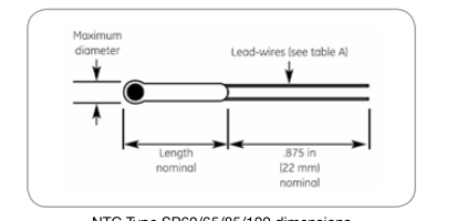
Thermal and Electrical Properties
The following table lists the thermal and electrical properties for all ultra-stable probe thermistors. All definitions and test methods are per MIL-
PRF-23648
Table A
Thermistor Type
SP60
SP65
Body Dimensions
.060 in (1.5 mm)
.065 in (1.6 mm)
Max. Diameter
Standard Lengths
Code “A”
.125 in (3.2 mm)
.125 in (3.2 mm)
Code “B”
.250 in (6.3 mm)
.250 in (6.3 mm)
Code “D”
.500 in (12.7 mm)
.500 in (12.7 mm)
Lead-wires
Nominal Diameter
.008 in (.20 mm)
.008 in (.20 mm)
Minimum Lead Length
.875 in (22 mm)
.875 in (22 mm)
Lead Material
Class “A” 200°F (105°C)
Tinned Dumet
Tinned Dumet
Class “B” 392°F (200°C)
Platinum Alloy
Platinum Alloy
Class “C” 572°F (300°C)
Platinum Alloy
Platinum Alloy
Thermal Time Constant
Still Air at 77°F (25°C)
12 sec
13 sec
Plunge into Water
300 msec
320 msec
Dissipation Constant
Still Air at 77°F (25°C)
.60 mW/°C
.65 mW/°C
Still Water at 77°F (25°C)
3.00 mW/°C
3.30 mW/°C
Power Rating (in air)
100% Maximum Power Rating @ 77°F (25°C) .048 Watts
.052 Watts
See Class
See Class
Derated to 0% @ Maximum Temperature
NTC Type SP60/65/85/100 dimensions
SP85
SP100
.085 in (2.1 mm)
.100 in (2.5 mm)
.125 in (3.2 mm)
.125 in (3.2 mm)
.250 in (6.3 mm)
.250 in (6.3 mm)
.500 in (12.7 mm)
.500 in (12.7 mm)
.012 in (.30 mm)
.012 in (.30 mm)
.875 in (22 mm)
.875 in (22 mm)
Tinned Dumet
Tinned Dumet
Platinum Alloy
Platinum Alloy
Platinum Alloy
Platinum Alloy
16 sec
22 sec
400 msec
600 msec
.85 mW/°C
1.00 mW/°C
4.00 mW/°C
5.00 mW/°C
.068 Watts
.080 Watts
See Class
See Class
Page 3
Stability Classes (By Nominal Resistance at 77°F (25°C)
Ultra-stable probe thermistors availability depends upon nominal resistance at 77°F (25°C). Stability class is indicated by a code letter for temperature class and a code number for stability group.
Example: “A1” = .02% maximum change per year at 221°F (105°C) maximum temperature.
Table B
Material System (All Types 60/65/85/100)
| Code Letter | R-vs-T Curve | 25/125 Ratio | Nominal Resistance Range @ 77°F (25°C) Ohms (W) | Code Class “A” 221°F (105°C) maximum | Class “B” 392°F (200°C) maximum | Class “C” 572°F (300°C) maximum |
|---|---|---|---|---|---|---|
| E | 0 | 5.0 | 30 to 51 | – – – – – A6 | – – – | – – C6 |
| A | 1 | 11.8 | 51 to 150 | – – A3 A4 A5 A6 | – – B6 | – – C6 |
| A | 2 | 12.5 | 150 to 360 | – – A3 A4 A5 A6 | – – B6 | – – C6 |
| A | 3 | 14.0 | 360 to 750 | – – A3 A4 A5 A6 | – – B6 | – – C6 |
| A | 4 | 16.9 | 750 to 1.5k | A1 A2 A3 A4 A5 A6 | – B5 B6 | – – C6 |
| A | 5 | 19.8 | 1.5k to 3.6k | A1 A2 A3 A4 A5 A6 | – B5 B6 | – – C6 |
| A | 6 | 22.1 | 3.6k to 6.2k | A1 A2 A3 A4 A5 A6 | – B5 B6 | – – C6 |
| A | 7 | 22.7 | 6.2k to 9.1k | A1 A2 A3 A4 A5 A6 | – B5 B6 | – – C6 |
| B | 8 | 29.4 | 9.1k to 27k | A1 A2 A3 A4 A5 A6 | – B5 B6 | – – C6 |
| B | 9 | 30.8 | 27k to 43k | – A2 A3 A4 A5 A6 | – B5 B6 | – – C6 |
| B | 10 | 32.3 | 43k to 75k | – A2 A3 A4 A5 A6 | – B5 B6 | – – C6 |
| B | 11 | 35.7 | 75k to 160k | – A2 A3 A4 A5 A6 | – B5 B6 | – – C6 |
| B | 12 | 38.1 | 160k to 360k | – A2 A3 A4 A5 A6 | – B5 B6 | – – C6 |
| B | 13 | 45.0 | 360k to 750k | – A2 A3 A4 A5 A6 | – B5 B6 | – – C6 |
| B | 14 | 48.1 | 750k to 1.5M | – A2 A3 A4 A5 A6 | – B5 B6 | – – C6 |
| B | 15 | 56.5 | 1.5M to 3.0M | – – – A4 A5 A6 | – – B6 | – – C6 |
| D | 16 | 75.6 | 3.0M to 8.2M | – – – A4 A5 A6 | – – B6 | – – C6 |
| D | 17 | 81.0 | 8.2M to 20M | – – – A4 A5 A6 | – – B6 | – – C6 |
“1” = 0.02%/year
“2” = 0.05%/year
“3” = 0.075%/year
“4” = 0.1%/year
“5” = 0.2%/year
“6” = 0.5%/year
Page 4
Ordering Information
The code number to be ordered may be specified as follows: Code
Model Number
SP
60
SP
65
SP
85
SP
100 Code Probe Length A 1/8 in (3.175 mm) B 1/4 in (6.35 mm) D 1/2 in (12.7 mm) Code Material System Code X See table B for codes Code Zero-power resistance @ 77°F (25°C)\*\* 202 See Note 2 Code Tolerance\* F 1 G 2 J 5 K 10 L 15 M 20 N 25 P 30 Q 40 R 50 Non-standard (specify value) S Code Temperature Class Stability 221°F (105°C) maximum A 392°F (200°C) maximum B 572°F (300°C) maximum C Code Group (Resistance Change) 1 .02% per year 2 .05% per year 3 .075% per year 4 .1% per year 5 .2% per year 6 .5% per year
SP ____ - ____ - ____ - ____ - ____ - ____ - ____ Typical model number
\*Special tolerances are available on request. Consult the factory for special resistance tolerances, non-standard resistances and/or nonstandard temperatures.
\*\*The zero-power resistance at 77°F (25°C), expressed in ohms, is identified by a three digit code number. The first two digits represent significant figures, and the last digit specifies the number of zeros to follow. Example: 2k Ohms =“202”. The standard resistance values are from the 24-Value series decade as specified in Military Standard MS90178. 1.0 / 1.1 / 1.2 / 1.3 / 1.5 / 1.6 / 1.8 / 2.0 / 2.2 / 2.4 / 2.7 / 3.0 3.3 / 3.6 / 3.9 / 4.3 / 4.7 / 5.1 / 5.6 / 6.2 / 6.8 / 7.5 / 8.2 / 9.1
Amphenol
Advanced Sensors
www.amphenol-sensors.com
© 2014 Amphenol Corporation. All Rights Reserved. Specifications are subject to change without notice. Other company names and product names used in this document are the registered trademarks or
trademarks of their respective owners.