
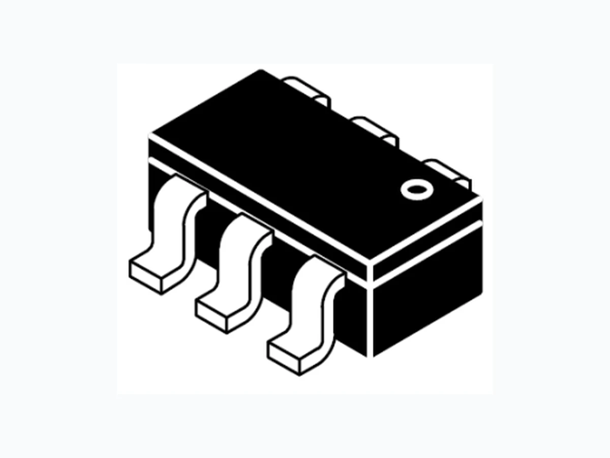
SP3051-04HTG LEIDITECH
Document overview
- Manufacturer or author: Provided By www.digicamel.com(FREE DATASHEET DOWNLOAD SITE)
- PDF pages: 8
Technical content
Features
Ultra low leakage: nA level Operating voltage: 5V Low clamping voltage Complies with following standards: – IEC 61000-4-2 (ESD) immunity test Air discharge: ±30kV Contact discharge: ±30kV – IEC61000-4-4 (EFT) 40A (5/50ns) – IEC61000-4-5 (Lightning) 25A (8/20μs) RoHS Compliant
Applications
USB 2.0 power and data line Set-top box and digital TV Digital video interface (DVI) Notebook Computers SIM Ports Dimensions SOT-26 Pin Configuration Mechanical Characteristics Package: SOT-26 Lead Finish: Lead Free UL Flammability Classification Rating 94V-0 Quantity Per Reel:3,000pcs Reel Size:7inch Absolute Maximum Ratings (Tamb=25°C unless otherwise specified) Parameter Symbol Value Unit Peak Pulse Power (8/20µs) Ppp 500 W ESD per IEC 61000−4−2 (Air) V ESD ±30 Kv ESD per IEC 61000−4−2 (Contact) ±30 Operating Temperature Range T J -55 to +125 Storage Temperature Range T STJ -55 to +150 10/100/1000 Ethernet AEC-Q101 qualified. Rev : www.leiditech.com 01.06.2018 1/8 Device Marking: SRV05
Electrical Characteristics
(TA=25°C unless otherwise specified) Rev : www.leiditech.com 01.06.2018 2/8 Parameter Symbol Min Typ Max Unit Test Condition Reverse Working Voltage VRWM 5 V Breakdown Voltage VBR 6 V IT = 1mA, Pin 5 to Pin 2 Reverse Leakage Current IR 1 µA VRWM = 5V, Pin 5 to Pin 2 Forward Voltage VF 1.2 V IF = 15mA Clamping Voltage VC 12 V IPP = 1A (8 x 20µs pulse), any I/O pin to ground Clamping Voltage VC 20 V IPP = 25A (8 x 20µs pulse), any I/ O pin to ground Junction Capacitance CJ 1.5 pF VR = 0V, f = 1MHz, between I/O pins Junction Capacitance CJ 3.0 5.0 pF VR = 0V, f = 1MHz, any I/O pin to ground Note 1: I/O pins are Pin 1, 3, 4 and 6 SP3051-04HTG
Typical Performance Characteristics (TA=25°C unless otherwise Specified) Peak Pulse Power vs. Pulse Time Clamping Voltage vs. Peak Pulse Current Power Derating Curve
8 X 20μs Pulse Waveform ESD Clamping Voltage
8 kV Contact per IEC61000−4−2 100 120 0 25 50 75 100 125 150 % of Rated Power Ambient Temperature_Ta(℃) 100 0 20 40 60 80 % of Peak Pulse Current Time_t(uS) 0 1 2 3 4 5 Junction Capacitance_Cj (pF) Reverse Voltage_VR (V) Line to GND Line to Line Note:Data is taken with a 10x attenuator Rev : www.leiditech.com 01.06.2018 3/8 Junction Capacitance vs. Reverse Voltage SP3051-04HTG
The SP3051-04HTG is designed to protect four data lines from transient ov-ervoltages by clamping them to fixed reference. When the voltage on the protected line exceeds the reference voltage (plus diode VF) the steering diodes are for ward biased, conducting the transient current away from the sensitive circuitry. Data lines are connected at pins 1, 3, 4 and 6. The negative reference (REF1) is connected at pin 2. This pin should be connected directly to a ground plane on the board for best results. The path length is kept as short as possible to minimize parasitic inductance. The positive reference (REF2) is connected at pin 5. I O I O I O I O T o P r o t e c t e d I C T o P r o t e c t e d I C V C C SP3051-04HTG on Video Interface Application 1 2 3 6 5 4 1 2 3 6 5 4 VCC VCC Rev : www.leiditech.com 01.06.2018 4/8 SP3051-04HTG
SP3051-04HTG on USB Port Application SP3051-04HTG on SIM Port Application V b u s V b u s D D G N D V b u s D D G N D U S B C o n t r o l l e r U S B P o r t U S B P o r t 1 2 3 6 5 4 I/O Clock Vcc GND SIM Reset Rev : www.leiditech.com 01.06.2018 5/8 SP3051-04HTG
SP3051-04HTG on Digital Visual Interface (DVI) Application SP3051-04HTG on Ethernet 10/100 (Differential mode) Application T X T X R X R X V C C G N D C o u p l i n g T r a n s f o r m e r T X T X R X R X R J C o n n e c t o r V G A T X T X T X T X T X T X T C T C R X R X R X R C R C R X R X R X L C D P C G r a p h i c s C a r d F l a t P a n e l D i s p l a y D M T r a n s m i t t e r T M D S R e c e i v e r Rev : www.leiditech.com 01.06.2018 6/8 SP3051-04HTG
SP3051-04HTG on T1/E1 Interface Application V C C R T I P R R I N G T T I P T R I N G T E T r a n c e i v e r R R R R T T Rev : www.leiditech.com 01.06.2018 7/8 SP3051-04HTG
Min. Nom. Max. Min. Nom. Max. A 0.035 - 0.057 0.90 - 1.45 0.000 0.006 0.00 0.15 b 0.010 0.020 0.25 0.50 c 0.003 - 0.009 0.08 - 0.22 D 0.110 0.114 0.122 2.80 2.90 3.10 E
0.110 BSC
2.80 BSC
e 0.037 BSC 0 .95 BSC
0.075 BSC
1.90 BSC
(0.024) (0.60) aaa 0.004 0.10 bbb 0.008 0.20 ccc 0.008 0.20 Symbol Inches Millimeters C (0.098) (2.50) G 0.055 1.40 P 0.037 0.95 X 0.024 0.60 Y 0.043 1.10 Z 0.141 3.60 Soldering Footprint θ Shanghai Leiditech Electronic Co.,Ltd Email: sale1@leiditech.com Tel : +86- 021 50828806 Fax : +86- 021 50477059 Rev : www.leiditech.com 01.06.2018 8/8 SP3051-04HTG