

 Download PDF
SMV1130_15 SKYWORKS
Document overview
- PDF pages: 8
Technical content
Page 1
DATA SHEET
SMV1130 Series: Hyperabrupt Junction Tuning Varactors
Applications
High-volume, low-cost systems Wideband VCOs
Features
High tuning ratio Low series resistance Packages rated MSL1, 260 °C per JEDEC J-STD-020
Skyworks GreenTM products are compliant with all applicable legislation and are halogen-free. For additional information, refer to Skyworks Definition of GreenTM, document number SQ04–0074.
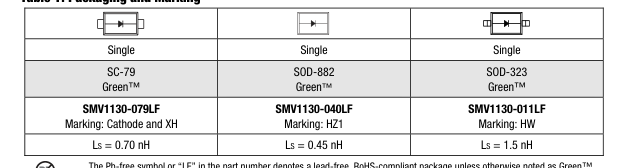
Table 1. Packaging and Marking
Description
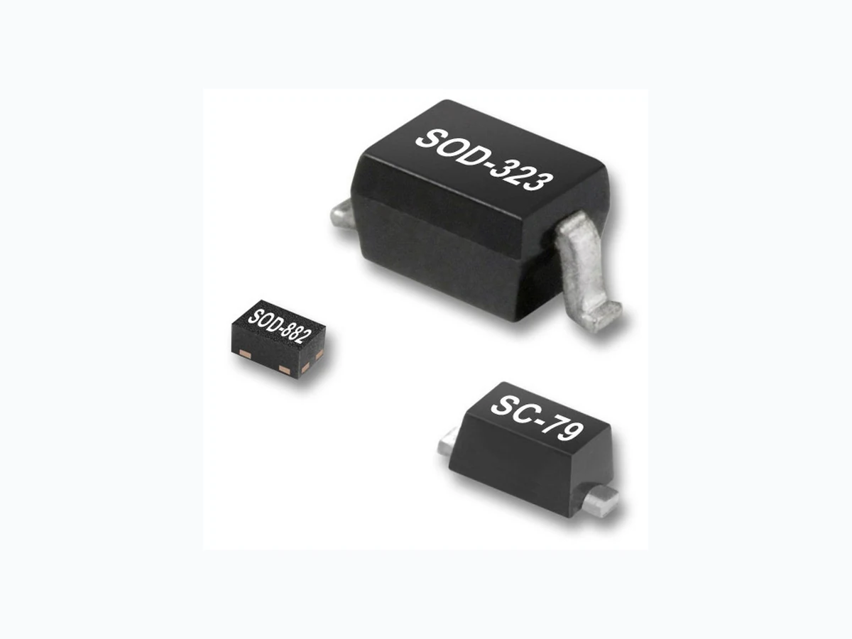
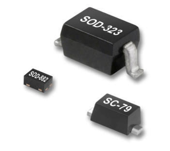
The SMV1130 series of surface mount hyperabrupt junction varactor diodes are designed for very high capacitance tuning ratios with a low series resistance, which makes these devices especially attractive for wideband Voltage-Controlled Oscillator (VCO) applications. Table 1 describes the packages and markings of the SMV1130 varactors.
Tin/lead (Sn/Pb) packaging is not recommended for new designs.
Page 2
Electrical and Mechanical Specifications
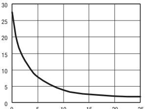
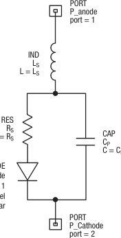
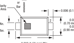
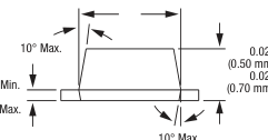
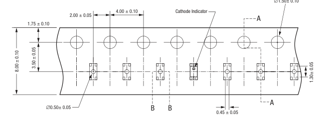
The absolute maximum ratings of the SMV1130 varactors are provided in Table 2. Electrical specifications are provided in Table 3. Typical capacitance values are listed in Table 4. Typical capacitance versus voltage performance for the SMV1130 varactors is illustrated in Figure 1. The SPICE model for the SMV1130 varactor series is shown in Figure 2 and the associated model parameters are provided in Table 5. Package dimensions are shown in Figures 3, 5 and 7, and tape and reel drawings are provided in Figures 4, 6, and 8.
Table 2. SMV1130 Series Absolute Maximum Ratings (Note 1)
Package and Handling Information
Instructions on the shipping container label regarding exposure to moisture after the container seal is broken must be followed. Otherwise, problems related to moisture absorption may occur when the part is subjected to high temperature during solder assembly. The SMV1130 varactors are rated to Moisture Sensitivity Level 1 (MSL1) at 260 C. They can be used for lead or lead-free soldering. For additional information, refer to the Skyworks Application Note, Solder Reflow Information, document number 200164. Care must be taken when attaching this product, whether it is done manually or in a production solder reflow environment. Production quantities of this product are shipped in a standard
tape and reel format.
| Parameter | Symbol | Minimum | Maximum | Units |
|---|---|---|---|---|
| Reverse voltage | VR | 26 | V | |
| Forward current | IF | 20 | mA | |
| Power dissipation | PDIS | 250 | mW | |
| Operating temperature | TOP | –55 | +125 | C |
| Storage temperature | TSTG | –55 | +150 | C |
Note 1: Exposure to maximum rating conditions for extended periods may reduce device reliability. There is no damage to device with only one parameter set at the limit and all other parameters set at or below their nominal value. Exceeding any of the limits listed here may result in permanent damage to the device.
CAUTION: Although this device is designed to be as robust as possible, electrostatic discharge (ESD) can damage this device. This device must be protected at all times from ESD. Static charges may easily produce potentials of several kilovolts on the human body or equipment, which can discharge without detection. Industry-standard ESD precautions should be used at all times.
Table 3. SMV1130 Series Electrical Specifications (Note 1) (TOP = 25 C, Unless Otherwise Noted)

Note 1: Performance is guaranteed only under the conditions listed in this table.
Page 3
Table 4. Capacitance vs Reverse Voltage
| VR (V) | CT (pF) |
| 0 | 27.6 |
| 1 | 18.5 |
| 2.5 | 12.8 |
| 5 | 7.9 |
| 10 | 3.8 |
| 15 | 2.6 |
| 20 | 2.0 |
| 25 | 1.8 |
Typical Performance Characteristics
0 5 10 15 20 25
Reverse Voltage (V)
Figure 1. Capacitance vs Reverse Voltage
Page 4
DIODEM
FC = 0.5
Diode_Model
BV = 0
IS = 1.00e-14
IBV = 1e-3
RS = 0
ISR = 0
N = 1
NR = 2
TT = 0
IKF = 0
CJO = CJO
NBV = 1
R = RS
IBVL = 0
M = M VJ = VJ
NBVL = 1
EG = 1.11
TBV1 = 0
DIODE Varactor_Diode
XTI = 3
TNOM = 27
AREA = 1
KF =0
FFE = 1
MODEL = Diode_Model
AF =1
MODE = nonlinear
S1672
Figure 2. SPICE Model
Table 5. SPICE Model Parameters
| Part Number | CJO (pF) | VJ (V) | M | CP (pF) | RS (Ω) | LS (nH) |
|---|---|---|---|---|---|---|
| SMV1130-079LF | 25.8 | 10 | 3.7 | 1.8 | 0.8 | 0.70 |
| SMV1130-040LF | 25.8 | 10 | 3.7 | 1.8 | 0.8 | 0.45 |
| SMV1130-011LF | 25.8 | 10 | 3.7 | 1.8 | 0.8 | 1.50 |
Page 5
Box
Indicator Area
0.010 (0.25 mm) Min. 0.014 (0.35 mm) Max.
0.060 (1.50 mm) Min. 0.067 (1.70 mm) Max.
0.043 (1.10 mm) Min. 0.051 (1.30 mm) Max.
0.006 (0.15 mm) Min.
0.028 (0.70 mm) Min. 0.035 (0.90 mm) Max.
0.003 (0.07 mm) Min. 0.008 (0.20 mm) Max.
Dimensions are in inches (millimeters shown in parentheses)
Figure 3. SC-79 Package Dimensions
(0.50 mm) Min.
(0.70 mm) Max.
S1652
∅1.50± 0.10
0.19
0.90 ± 0.05
1.94 ± 0.05
B
Notes: 1. Carrier tape: black conductive polycarbonate. 2. Cover tape: transparent conductive material.
0.73 ± 0.05
- Cover tape size: 5.4 mm width. 4. ESD surface resistivity is ≥1 x 10⁴ ~ ≤ 1 x 10⁸ Ohms/square.
A
- All measurements are in millimeters. 6. Standard reel size is 7 inches. Standard reel quantity is 3000 pcs.
S2188
Figure 4. SC-79 Tape and Reel Dimensions
Page 6
0.03 C Seating Plane
5 0.05/0.00
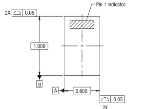
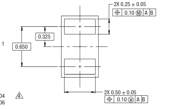
C
Terminal 1
0.46 + 0.04 –0.06
NOTES: 1. All measurements are in millimeters. 2. Dimensions and tolerances according to ASME Y14.5M-1994. 3. These packages are used principally for discrete devices. 4. This dimension includes stand-off height and package body thickness, but does not include attached features, e.g., external heatsink or chip capacitors. An integral heatslug is not considered an attached feature. 5. This dimension is primarily terminal plating, but does not include small metal protrusion.
Y1410
Figure 5. SOD-882 Package Dimensions
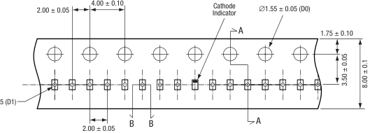
0.20
∅0.40 ± 0.05 (D1)
0.47 ± 0.05 (Ko)
A
0.70 ± 0.05 (A0)
Notes: 1. Carrier tape: black conductive polycarbonate. 2. Cover tape: transparent conductive material. 3. Cover tape size: 5.4 mm width. 4. ESD surface resistivity is ≥1 x 10⁴ ~ ≤ 1 x 10⁸ Ohms/square.
B
- All dimensions are in millimeters.
S1922
Figure 6. SOD-882 Tape and Reel Dimensions
Page 7
0.060 (1.52 mm) Min. 0.070 (1.78 mm) Max.
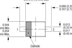
(1.12 mm) Min.
(1.37 mm) Max.
Indicator
0.090 (2.29 mm) Min. 0.107 (2.72 mm) Max.
0.000 (0 mm) Min. 0.004 (0.10 mm) Max.
(0.33 mm) Min.
(0.43 mm) Max.
0.012 (0.305 mm) Min. 0.016 (0.406 mm) Max.
0.036 (0.91 mm) Min. 0.046 (1.17 mm) Max.
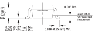
(0.635 mm) Min.
(0.940 mm) Max.
0.008 (0.203 mm) Max.
0.018 (0.46 mm) Max.
Dimensions are in inches (millimeters shown in parentheses)
S1619
Figure 7. SOD-323 Package Dimensions
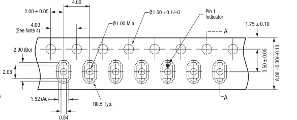
0.30 ± 0.05
R0.3 Max.
1.35 (Ko)
1.07 (K1)
A
Notes: 1. Carrier tape: black conductive polystyrene. 2. Cover tape: transparent conductive PSA. 3. Cover tape size: 5.4 mm width. 4. 10 sprocket hole pitch cumulative tolerance: ±0.20 mm. 5. All measurements are in millimeters.
S2910
Figure 8. SOD-323 Tape and Reel Dimensions
Page 8
Copyright © 2002-2007, 2009-2012, 2014-2015 Skyworks Solutions, Inc. All Rights Reserved.
Information in this document is provided in connection with Skyworks Solutions, Inc. (“Skyworks”) products or services. These materials, including the information contained herein, are provided by Skyworks as a service to its customers and may be used for informational purposes only by the customer. Skyworks assumes no responsibility for errors or omissions in these materials or the information contained herein. Skyworks may change its documentation, products, services, specifications or product descriptions at any time, without notice. Skyworks makes no commitment to update the materials or information and shall have no responsibility whatsoever for conflicts, incompatibilities, or other difficulties arising from any future changes.
No license, whether express, implied, by estoppel or otherwise, is granted to any intellectual property rights by this document. Skyworks assumes no liability for any materials, products or information provided hereunder, including the sale, distribution, reproduction or use of Skyworks products, information or materials, except as may be provided in Skyworks Terms and Conditions of Sale.
THE MATERIALS, PRODUCTS AND INFORMATION ARE PROVIDED “AS IS” WITHOUT WARRANTY OF ANY KIND, WHETHER EXPRESS, IMPLIED, STATUTORY, OR OTHERWISE, INCLUDING FITNESS FOR A PARTICULAR PURPOSE OR USE, MERCHANTABILITY, PERFORMANCE, QUALITY OR NON-INFRINGEMENT OF ANY INTELLECTUAL PROPERTY RIGHT; ALL SUCH WARRANTIES ARE HEREBY EXPRESSLY DISCLAIMED. SKYWORKS DOES NOT WARRANT THE ACCURACY OR COMPLETENESS OF THE INFORMATION, TEXT, GRAPHICS OR OTHER ITEMS CONTAINED WITHIN THESE MATERIALS. SKYWORKS SHALL NOT BE LIABLE FOR ANY DAMAGES, INCLUDING BUT NOT LIMITED TO ANY SPECIAL, INDIRECT, INCIDENTAL, STATUTORY, OR CONSEQUENTIAL DAMAGES, INCLUDING WITHOUT LIMITATION,
LOST REVENUES OR LOST PROFITS THAT MAY RESULT FROM THE USE OF THE MATERIALS OR INFORMATION, WHETHER OR NOT THE RECIPIENT OF MATERIALS HAS BEEN ADVISED OF THE POSSIBILITY OF SUCH DAMAGE.
Skyworks products are not intended for use in medical, lifesaving or life-sustaining applications, or other equipment in which the failure of the Skyworks products could lead to personal injury, death, physical or environmental damage. Skyworks customers using or selling Skyworks products for use in such applications do so at their own risk and agree to fully indemnify Skyworks for any damages resulting from such improper use or sale.
Customers are responsible for their products and applications using Skyworks products, which may deviate from published specifications as a result of design defects, errors, or operation of products outside of published parameters or design specifications. Customers should include design and operating safeguards to minimize these and other risks. Skyworks assumes no liability for applications assistance, customer product design, or damage to any equipment resulting from the use of Skyworks products outside of stated published specifications or parameters.
Skyworks and the Skyworks symbol are trademarks or registered trademarks of Skyworks Solutions, Inc., in the United States and other countries. Third-party brands and names are for identification purposes only, and are the property of their respective owners. Additional information, including relevant terms and conditions, posted at www.skyworksinc.com, are incorporated by reference.