
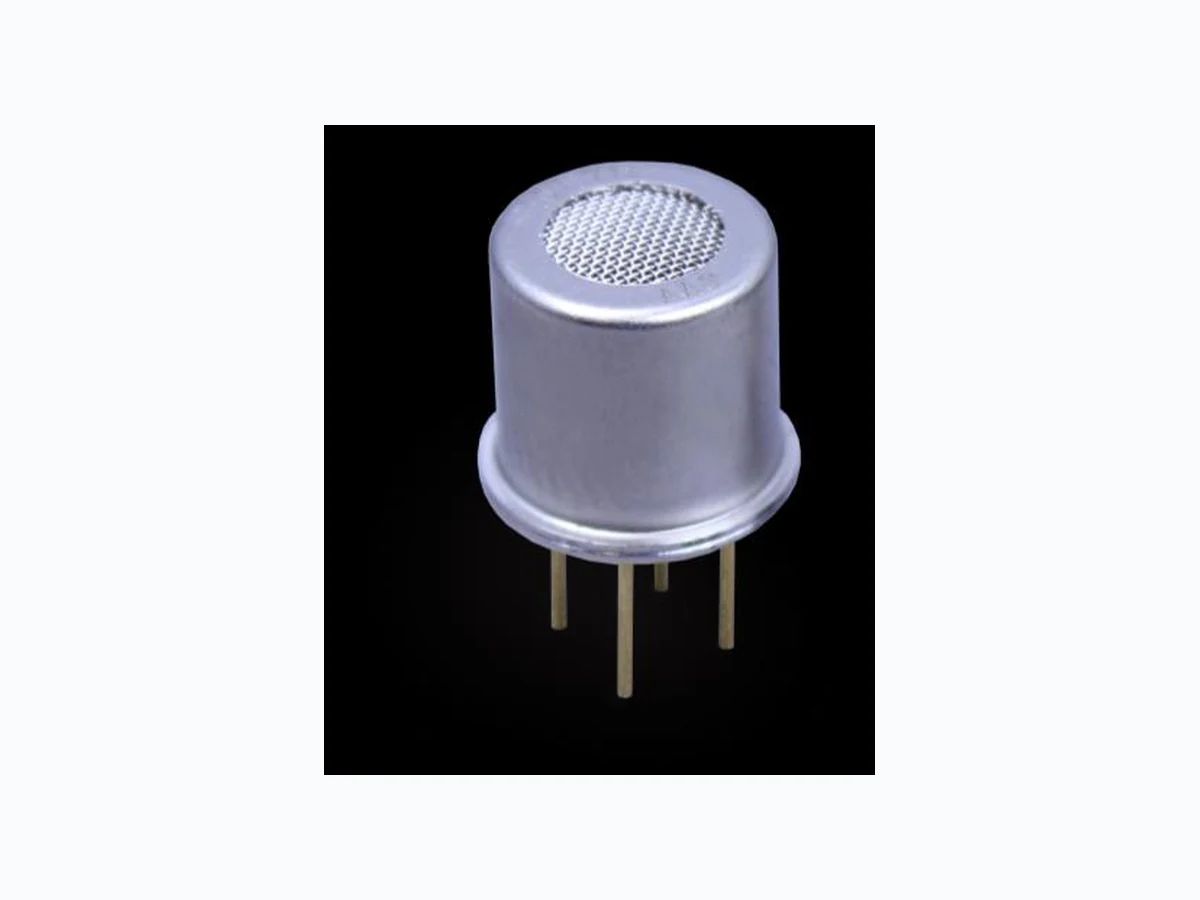
SGAS711 RENESAS
Document overview
- Manufacturer or author: Provided By www.digicamel.com(FREE DATASHEET DOWNLOAD SITE)
- PDF pages: 16
Technical content
Datasheet sections
- 6.1 Constant Voltage Drive
- 6.2 Constant Current Drive
- 6.3 Pulse-Width Modulation
- 6.4 Operating the Sensor at Temperature Extremes
- 7.1 Sensitivity
- 7.2 Response and Recovery Time
- 7.3 Cross-Sensitivity
Features
High sensitivity to a wide range of flammable gases Non-specific response; capable of being calibrated to detect a wide range of flammable gases Long lifetime (several years in typical applications) Typical response time < 30 seconds to 90% of full scale Environmental temperature range: -20°C to 50°C Minimal response to environmental humidity over the range of 0% to 95%, non-condensing Rugged, reliable sensor based on IDT’s exclusive technology TO-39 package Typical Applications Leak Detection Gas Concentration Detection Process Control Examples of Target Gases Hydrocarbons (HC) Hydrogen Liquid Petroleum Gas (LPG) Methane Natural Gas Propane Pentane R410a Available Support Evaluation kit – SMOD711 Smart Sensing Module Application notes Instruction videos Reference designs
Figure 2. Pin Assignments for SGAS711 – Top View Table 1. Pin Descriptions Note: See Figure 4 for the connections described below.
1 Heater + Positive input for VH heater voltage supply
2 Sensor + High-side of resistive sensor element; positive input for sensing voltage VC
3 Heater – Negative input for VH heater voltage supply (ground)
Note: All measurements were made in dry gas at room temperature. Specifications are subject to change. Table 2. Electrical Specifications
Table 3. Temperature Specifications durations will not will not harm the sensor. orders of magnitude across the sensing range. This shows that log resistance versus log concentration is linear. circuitry exacerbate these challenges and must be understood in order to account for or eliminate these effects.
- Heater Driver Circuits and Control
constant temperature) control of the heater.
6.1 Constant Voltage Drive
the temperature of the heater (and consequently gas sensitivity), voltage regulation is required. An easily implemented control circuit utilizes a three terminal voltage regulator, with the LM317 serving as an example as shown in Figure 5. Figure 5. Three Terminal Voltage Regulator three terminal voltage regulators is available from component manufacturers.
6.2 Constant Current Drive
and feedback control of the heater is possible through a simple measurement of the resultant voltage on the heater. well as the heater. Limiting the supply voltage to several hundred mV above the highest required drive voltage will help increase circuit efficiency. Figure 6. Voltage-Controlled Constant Current Circuit
6.3 Pulse-Width Modulation
sufficient testing at IDT to allow us to recommend it for any sensors in the SGAS family. Voltage to the heater should not exceed the maximum voltage allowed for a given heater family. A low-pass filter should be considered as part of the sensor signal circuit path to reduce noise from heater PWM.
6.4 Operating the Sensor at Temperature Extremes
temperature set point voltage versus environmental temperature is shown in Figure 7. Figure 7. Recommended Applied Heater Voltage as a Function of Environmental Temperature
sensor specifications, refer to Table 2.
7.1 Sensitivity
the resistance in air (RAir) and the resistance in gas (RGas). Figure 8. Sensor Response to a Variety of Flammable Gases
The typical response of the sensor to changes in humidity is shown in Figure 9. Figure 9. Effect of Different Humidity Levels on Sensor Signal at Ambient Temperature
7.2 Response and Recovery Time
operated with or without a pump or other source of external flow. Figure 10. Typical Sensor Response to Step Changes in Methane Concentration for Seven
7.3 Cross-Sensitivity
The response of the SGAS711 sensors to a range of other common gases is shown in Figure 11. Figure 11. Typical Sensor Response to other Common Gases
Table 4. Maximum ESD Ratings
- Mechanical Stress Testing
The qualification of the SGAS711 is based on the JEDEC standard (JESD47). given in this document. For information on constant acceleration test conditions and limits, contact IDT (see contact information on last page). Table 5. Mechanical Stress Test Conditions
- Package Drawing and Dimensions
Figure 12. TO-39 Package (TO4) Outline Drawing PSC-4676
© 2017 Integrated Device Technology, Inc. 15 October 24, 2017 11. Applications and Use Conditions The SGAS711 sensor is designed for gas leak detection and measurement of ppm levels of flammable gases. The sensor is not intended, recommended, or approved for use in safety or life-protecting applications or in potentially explosive environments. IDT disclaims all liability for such use. For sensor storage, IDT strongly recommends a dust and VOC free atmosphere, e.g. in synthetic air. 12. Ordering Information Orderable Part Number Description and Package MSL Rating Shipping Packaging Temperature SGAS711 4-pin TO-39 (TO4) 1 Tray -20°C to +50°C SMOD711KITV1 SMOD711 Evaluation Kit, including the SMOD711 Smart Sensing Module (includes the SGAS711 sensor), mini-USB cable, and wall-mounted 9V power supply. The SMOD7xx Application Software is available for download at www.idt.com/SMOD711. 13. Revision History Revision Date Description of Change October 24, 2017 Full revision. November 4, 2016 Changed to IDT branding. Corporate Headquarters
6024 Silver Creek Valley Road
San Jose, CA 95138 www.IDT.com Sales 1-800-345-7015 or 408-284-8200 Fax: 408-284-2775 www.IDT.com/go/sales Tech Support www.IDT.com/go/support DISCLAIMER Integrated Device Technology, Inc. (IDT) and its affiliated companies (herein referred to as “IDT”) reserve the ri ght to modify the products and/or specifications described herein at any time, without notice, at IDT's sole discretion. Performanc e specifications and operating parameters of the described products are determined in an independent state and are not guaran teed to perform the same way when installed in customer products. The information contained herein is provided without representati on or warranty of any kind, whether express or implied, including, but not limited to, the suitability of IDT's products for any particular purpose, an implied warranty of merchantability, or non -infringement of the intellectual property rights of others. This document is presented only as a guide and does not convey any license under intellectual property rights of IDT or any third parties. IDT's products are not intended for use in applications involving extreme environmental conditions or in life suppor t systems or similar devices where the failure or malfunction of an IDT product can be reasonably expected to significantly affect the health or safety of users. Anyone using an IDT product in such a manner does so at their own risk, absent an express, wri tten agreement by IDT. Integrated Device Technology, IDT and the IDT logo are trademarks or registered trademarks of IDT and its subsidiaries in the United States and other countries. Other trademarks used herein are the property of IDT or their respectiv e third party owners. For datasheet type definitions and a glossary of common terms, visit www.idt.com/go/glossary . All contents of this document are copyright of Integrated Device Technology, Inc. All rights reserved.
TOYOSU FORESIA, 3-2-24 Toyosu, Koto-ku, Tokyo 135-0061, Japan www.renesas.com Contact Information For further information on a product, technology, the most up-to-date version of a document, or your nearest sales office, please visit: www.renesas.com/contact/ Trademarks Renesas and the Renesas logo are trademarks of Renesas Electronics Corporation. All trademarks and registered trademarks are the property of their respective owners. IMPORTANT NOTICE AND DISCLAIMER RENESAS ELECTRONICS CORPORATION AND ITS SUBSIDIARIES (“RENESAS”) PROVIDES TECHNICAL SPECIFICATIONS AND RELIABILITY DATA (INCLUDING DATASHEETS), DESIGN RESOURCES (INCLUDING REFERENCE DESIGNS), APPLICATION OR OTHER DESIGN ADVICE, WEB TOOLS, SAFETY INFORMATION, AND OTHER RESOURCES “AS IS” AND WITH ALL FAULTS, AND DISCLAIMS ALL WARRANTIES, EXPRESS OR IMPLIED, INCLUDING, WITHOUT LIMITATION, ANY IMPLIED WARRANTIES OF MERCHANTABILITY, FITNESS FOR A PARTICULAR PURPOSE, OR NON-INFRINGEMENT OF THIRD PARTY INTELLECTUAL PROPERTY RIGHTS. These resources are intended for developers skilled in the art designing with Renesas products. You are solely responsible for (1) selecting the appropriate products for your application, (2) designing, validating, and testing your application, and (3) ensuring your application meets applicable standards, and any other safety, security, or other requirements. These resources are subject to change without notice. Renesas grants you permission to use these resources only for development of an application that uses Renesas products. Other reproduction or use of these resources is strictly prohibited. No license is granted to any other Renesas intellectual property or to any third party intellectual property. Renesas disclaims responsibility for, and you will fully indemnify Renesas and its representatives against, any claims, damages, costs, losses, or liabilities arising out of your use of these resources. Renesas' products are provided only subject to Renesas' Terms and Conditions of Sale or other applicable terms agreed to in writing. No use of any Renesas resources expands or otherwise alters any applicable warranties or warranty disclaimers for these products. (Rev.1.0 Mar 2020) © 2020 Renesas Electronics Corporation. All rights reserved.