
 Download PDF
SMM BEL
Document overview
- PDF pages: 2
Technical content
Page 1


Electrical Characteristics
| Testing Current | Blow Time | |
| Minimum | Maximum | |
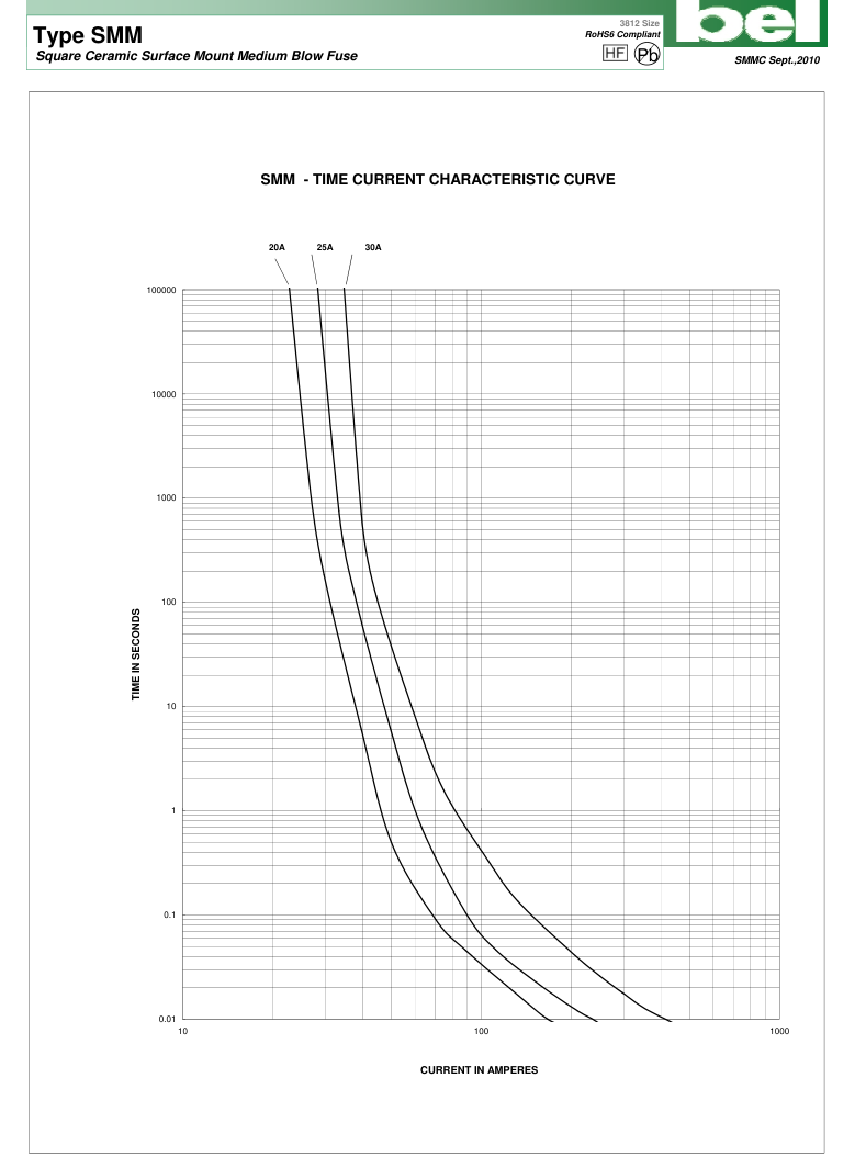
| 100% | 4 hrs | N/A |
| 200% | N/A | 60 sec |
Approvals
| Safety Agency Approvals | Amp range / I.R. ability @ Volt |
| Recognized File No. E20624 | 20A - 30A / 100A@ 250V AC resistive 150A@125V AC resistive 300A@ 65V DC resistive |
Soldering Guidelines
Reflow Conditions Recommended: 240°C, 30 sec. max.
Pb-Free Process Compatibility: When soldered to test boards using IR reflow in accordance with JEDEC J-STD-020 (260°C, 40 sec. max.), SMM samples exhibited DCR change of +10% to -20% from initial values. Subsequent tests showed all samples complied with the stated electrical characteristics on this data sheet.
NOT Recommended for Wave solder / Direct immersion / Hand Solder
Environmental Specification
Shock Resistance MIL-STD-202G, Method 213B, Test Condition I (100 G's peak for 6 milliseconds).
Vibration Resistance MIL-STD-202G, Method 201A (10-55 Hz, 0.06 inch, total excursion).
Salt Spray Resistance
MIL-STD-202G, Method 101E, Test condition B (48 hrs).
Thermal Shock Resistance MIL-STD-202G, Method 107G, Test Condition B (-65°C to +125°C)
Insulation Resistance:
MIL-STD-202G, Method 302, Test Condition A
(After Opening) 10,000 ohms minimum
Solderability:
MIL-STD-202G, Method 208H
Soldering Heat Resistance:
MIL-STD-202G, Method 210F
Operating Temperature
-55°C to +85°C Max.
NOTES:
– TEST CONDITIONS
| Catalog Number | Ampere Rating | Typical Cold Resistance (ohm) | Volt-drop @100% In (Volt) max. | Melting I²t @10In (A²Sec) min. | Maximum Power Dissipation (W) |
|---|---|---|---|---|---|
| SMM 20 | 20A | 0.0025 | 0.09 | 270 | 1.8 |
| SMM 25 | 25A | 0.0019 | 0.08 | 420 | 2.0 |
| SMM 30 | 30A | 0.0013 | 0.07 | 1000 | 2.1 |
Consult manufacturer for other ratings
Physical Specification
Materials Ceramic Body / Matte Tin Plated Brass Caps
Marking
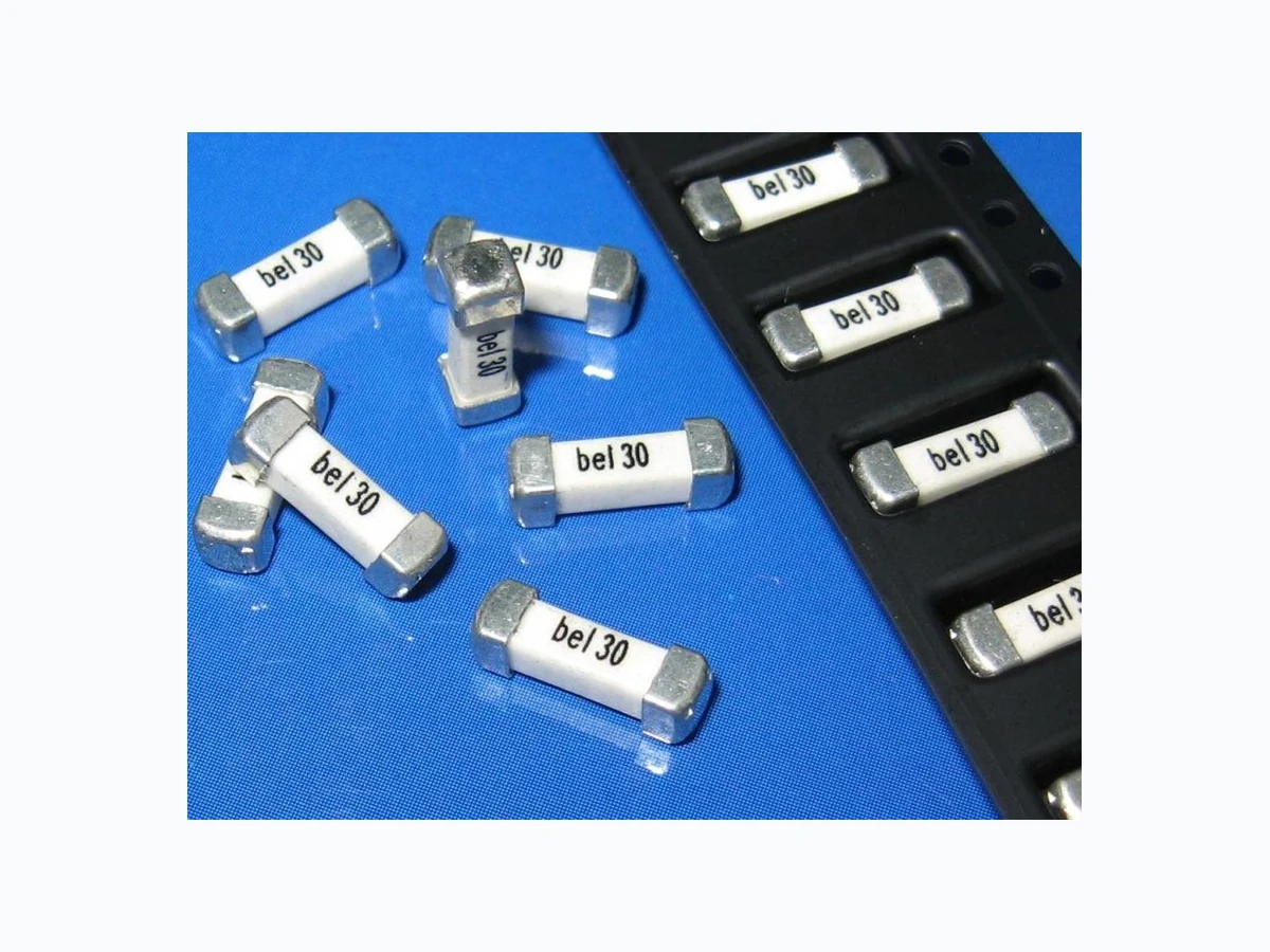
On fuse: "bel", "Current Rating" in black
'On label: "bel", "SMM", Current Rating, Voltage Rating, Interrupting Rating, Safety Logo and " "," "(China RoHS compliant)
Packaging
2,000 fuses in 13 inches dia. reel, 16mm wide tape, 8mm pitch, per EIA Standard 481
Mechanical Dimensions
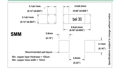
For all SMM data, as well as UL Component investigation, all tests were conducted with fuse samples soldered on a PCB (1.6mm thick) test board with copper traces measuring 0.1 mm nominal thickness (3 oz.clad), 10mm wide and 100 mm overall length.
– UL Condition of Acceptability - the following information is contained in the UL Component Recognition for SMM Fuse Series: The maximum temperature recorded in open air was 100 oC in a 21 oC ambient (79 oC rise). Consideration should be given to checking operating temperatures in end-use application with regard to thermal index of surrounding materials and components. (Maximum temperature recorded at 80% of rating (24A) for the SMM30 rating was 69 C (48 C rise).
CAUTION: – MINIMUM FUSING POINT :
The SMM Series fuses are NOT intended to be operated at currents between 100% and 200% of ampere rating. Prolonged operation at currents in this range may result in overheating of the fuse and/or desoldering of the fuse caps from the PCB pad.
Page 2