
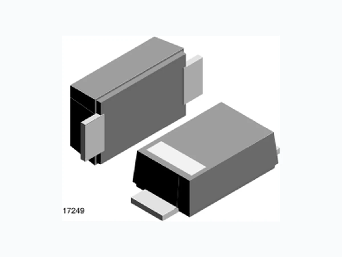
SMF22A-GS08 VISHAY
Document overview
- Manufacturer or author: Provided By www.digicamel.com(free datasheet download site)
- PDF pages: 8
Technical content
www.vishay.com Vishay Semiconductors Rev. 1.1, 17-Oct-13 1 Document Number: 85881 For technical questions, contact: ESDprotection@vishay.com THIS DOCUMENT IS SUBJECT TO CHANGE WITHOUT NOTICE. THE PRODUCTS DESCRIBED HEREIN AND THIS DOCUMENT ARE SUBJECT TO SPECIFIC DISCLAIMERS, SET FORTH AT www.vishay.com/doc?91000 Surface Mount ESD Protection Diodes MARKING (example only) Bar = cathode marking YY = type code (see table below) XX = date code
FEATURES
- For surface mounted applications
- Low-profile package
- Optimized for LAN protection applications
- Ideal for ESD protection of data lines in accordance with IEC 61000-4-2 (IEC 801-2)
- Ideal for EFT protecti on of data lines in accordance with IEC 61000-4-4 (IEC 801-4)
- ESD-protection acc. IEC 61000-4-2 ± 30 kV contact discharge ± 30 kV air discharge
- Low incremental surge resistance, excellent clamping capability
- 200 W peak pulse power capability with a 10/1000 μs waveform, repetition rate (duty cycle): 0.01 %
- “Low-Noise” technology - very fast response time
- High temperature soldering guaranteed: 260 °C/10 s at terminals
- e 3 - S n
- AEC-Q101 qualified
- Material categorization: For definitions of compliance please see www.vishay.com/doc?99912 17249 20278 1 2 YY 22623 XX Available Available
ORDERING INFORMATION
(EXAMPLE) ENVIRONMENTAL AND QUALITY CODE PACKAGING CODE ORDERING CODE (EXAMPLE)AEC-Q101 QUALIFIED RoHS-COMPLIANT + LEAD (Pb)-FREE TERMINATIONS TIN PLATED 3K PER 7" REEL (8 mm TAPE), 30K/BOX = MOQ 10K PER 13" REEL (8 mm TAPE), 50K/BOX = MOQSTANDARD HALOGEN-FREE SMF5V0A- E 3 -08 SMF5V0A-E3-08 SMF5V0A- M 3 -08 SMF5V0A-M3-08 SMF5V0A- H E 3 -08 SMF5V0A-HE3-08 SMF5V0A- H M 3 -08 SMF5V0A-HM3-08 SMF5V0A- E 3 -18 SMF5V0A-E3-18 SMF5V0A- M 3 -18 SMF5V0A-M3-18 SMF5V0A- H E 3 -18 SMF5V0A-HE3-18 SMF5V0A- H M 3 -18 SMF5V0A-HM3-18 PACKAGE DATA PACKAGE NAME MOLDING COMPOUND WEIGHT (mg) HEIGHT MAX. (mm) LENGTH MAX. (mm) WIDTH MAX. (mm) MOLDING COMPOUND MOISTURE SENSITIVITY LEVEL SOLDERING CONDITIONS SMF (DO-219AB) Standard 15 1.08 3.9 1.9 UL 94 V-0 MSL level 1 (according J-STD-020) 260 °C/10 s at terminalsHalogen-free
www.vishay.com Vishay Semiconductors Rev. 1.1, 17-Oct-13 2 Document Number: 85881 For technical questions, contact: ESDprotection@vishay.com THIS DOCUMENT IS SUBJECT TO CHANGE WITHOUT NOTICE. THE PRODUCTS DESCRIBED HEREIN AND THIS DOCUMENT ARE SUBJECT TO SPECIFIC DISCLAIMERS, SET FORTH AT www.vishay.com/doc?91000 ABSOLUTE MAXIMUM RATINGS (Tamb = 25 °C, unless otherwise specified) PARAMETER TEST CONDITIONS SYMBOL VALUE UNIT Peak pulse current t p = 10/1000 μs waveform I PPM see “Electrical Characteristics” A Peak pulse power tp = 8/20 μs waveform acc. IEC 61000-4-5 PPP 1000 W tp = 10/1000 μs waveform 200 W Peak forward surge current 8.3 ms single half sine-wave I FSM 50 A ESD immunity Contact discharge acc. IEC 61000-4-2; 10 pulses VESD ± 30 kV Air discharge acc. IEC 61000-4-2; 10 pulses ± 30 kV Thermal resistance Mounted on epoxy glass PCB with 3 mm x 3 mm, Cu pads ( 40 μm thick) RthJA 180 K/W Forward clamping voltage I F = 50A, tp = 400 μs V F 2.5 V Operating temperature Junction temperature T J - 55 to + 150 °C Storage temperature T STG - 55 to + 150 °C ELECTRICAL CHARACTERISTICS (Tamb = 25 °C, unless otherwise specified) PART NUMBER TYPE CODE REVERSE BREAKDOWN VOLTAGE at IT, tp = 5 ms TEST CURRENT REVERSE WORKING VOLTAGE REVERSE CURRENT at VRWM PEAK PULSE CURRENT tp = 10/1000 μs REVERSE CLAMPING VOLTAGE at IPPM CAPACITANCE at VR = 0 V, f = 1 MHz PROTECTION PATHS STD. HALOGEN- FREE VBR MIN. (V) IT (mA) VRWM (V) IR (μA) IPPM (A) VC MAX. (V) CD TYP. (pF) Nchannel SMF5V0A AE NE 6.40 10 5 5 21.7 9.2 1120 1 SMF6V0A AG NG 6.67 10 6 26 19.4 10.3 1063 1 SMF6V5A AK NK 7.22 10 6.5 20 17.9 11.2 938 1 SMF7V0A AM NM 7.78 10 7 3 16.7 12 843 1 SMF8V0A AR NR 8.89 1 8 0.1 14.7 13.6 706 1 SMF9V0A AV NV 10 1 9 0.1 13.5 15.4 640 1 SMF10A AX NX 11.1 1 10 0.1 11.8 17 562 1 SMF11A AZ NZ 12.2 1 11 0.1 11 18.2 509 1 SMF12A BE OE 13.3 1 12 0.1 10.1 19.9 483 1 SMF13A BG OG 14.4 1 13 0.1 9.3 21.5 423 1 SMF14A BK OK 15.6 1 14 0.1 8.6 23.2 392 1 SMF15A BM OM 16.7 1 15 0.1 8.2 24.4 367 1 SMF16A BP OP 17.8 1 16 0.1 7.7 26 343 1 SMF17A BR OR 18.9 1 17 0.1 7.2 27.6 324 1 SMF18A BT OT 20 1 18 0.1 6.8 29.2 320 1 SMF20A BV OV 22.2 1 20 0.1 6.2 32.4 283 1 SMF22A BX OX 24.4 1 22 0.1 5.6 35.5 271 1 SMF24A BZ OZ 26.7 1 24 0.1 5.1 38.9 244 1 SMF26A CE PE 28.9 1 26 0.1 4.8 42.1 230 1 SMF28A CG PG 31.1 1 28 0.1 4.4 45.4 227 1 SMF30A CK PK 33.3 1 30 0.1 4.1 48.4 207 1 SMF33A CM PM 36.7 1 33 0.1 3.8 53.3 198 1 SMF36A CP PP 40 1 36 0.1 3.4 58.1 178 1 SMF40A CR PR 44.4 1 40 0.1 3.1 64.5 172 1 SMF43A CT PT 47.8 1 43 0.1 2.9 69.4 165 1 SMF45A CV PV 50 1 45 0.1 2.8 72.7 162 1 SMF48A CX PX 53.3 1 48 0.1 2.6 77.4 161 1 SMF51A CZ PZ 56.7 1 51 0.1 2.4 82.4 151 1 SMF54A CA PA 60 1 54 0.1 2.25 88 148 1 SMF58A CC PC 64.4 1 58 0.1 2.1 95 144 1
www.vishay.com Vishay Semiconductors Rev. 1.1, 17-Oct-13 3 Document Number: 85881 For technical questions, contact: ESDprotection@vishay.com THIS DOCUMENT IS SUBJECT TO CHANGE WITHOUT NOTICE. THE PRODUCTS DESCRIBED HEREIN AND THIS DOCUMENT ARE SUBJECT TO SPECIFIC DISCLAIMERS, SET FORTH AT www.vishay.com/doc?91000 TYPICAL CHARACTERISTICS (Tamb = 25 °C, unless otherwise specified) Fig. 1 - ESD Discharge Current Wave Form acc. IEC 61000-4-2 (330 /150pF) Fig. 2 - 8/20 μs Peak Pulse Current Wave Form acc. IEC 61000-4-5 Fig. 3 - Peak Pulse Power Rating Fig. 4 - Pulse Waveform Fig. 5 - Typical Capacitance CD vs. Reverse Voltage VR Fig. 6 - Typical Capacitance CD vs. Reverse Voltage VR 0 % 20 % 40 % 60 % 80 % 100 % 120 % - 10 0 10 20 30 40 50 60 70 80 90 100 Time (ns) Discharge Current IESD Rise time = 0.7 ns to 1 ns 53 % 27 % 20557 0 % 20 % 40 % 60 % 80 % 100 % 01 0 2 0 3 0 4 0 Time (µs) IPPM 20 µs to 50 % 8 µs to 100 % 20548PPP - Peak Pulse Power (kW) 0.1 0.1 µs 1.0 µs 10 µs td - Pulse Width (s) 100 µs 1.0 ms 10 ms Non-repetitive pulse T A = 25 °C 17250 17415 t IRSM (%) 100 t1 = 10 µs t2 = 1000 µs 140 160 180 100 120 CD in pF 0.01 0.1 1 10 SMF43A SMF45A SMF48A SMF51A SMF54A SMF58A f = 1MHz VR in V22719 22720 100 150 200 250 300 0.01 0.1 1 10 SMF22A SMF24A SMF26A SMF28A SMF30A SMF33A SMF36A SMF40A f = 1MHz CD in pF VR in V
www.vishay.com Vishay Semiconductors Rev. 1.1, 17-Oct-13 4 Document Number: 85881 For technical questions, contact: ESDprotection@vishay.com THIS DOCUMENT IS SUBJECT TO CHANGE WITHOUT NOTICE. THE PRODUCTS DESCRIBED HEREIN AND THIS DOCUMENT ARE SUBJECT TO SPECIFIC DISCLAIMERS, SET FORTH AT www.vishay.com/doc?91000 Fig. 7 - Typical Capacitance CD vs. Reverse Voltage VR Fig. 8 - Typical Capacitance CD vs. Reverse Voltage VR Fig. 9 - Typical Reverse Voltage VR vs. Reverse Current IR Fig. 10 - Typical Reverse Voltage VR vs. Reverse Current IR Fig. 11 - Typical Reverse Voltage VR vs. Reverse Current IR Fig. 12 - Typical Reverse Voltage VR vs. Reverse Current IR
22721 CD in pF
0.01 0.1 1 10 SMF SMF11A SMF12A SMF13A SMF14A SMF15A SMF16A SMF17A SMF18A SMF20A f = 1MHz
22722 CD in pF
0.01 0.1 1 10 SMF8V0 SMF5V0A SMF6V0A SMF6V5A SMF7V0A SMF7V5A SMF8V0A SMF8V5A SMF9V0A SMF10A f = 1MHz
22723 VR in V
IR in μA 0.01 1 100 10 000 TJ = Junction Temperature = 25 °C SMF8V0A SMF7V5A SMF7V0A SMF6V5A SMF6V0A SMF5V0A
22724 VR in V
IR in μA 0.01 1 100 10 000 SMF16A SMF15A SMF14A SMF13A SMF12A SMF11A SMF10A SMF9V0A SMF8V5A TJ = Junction Temperature = 25 °C
22725 VR in V
IR in μA 0.01 1 100 10 000 TJ = Junction Temperature = 25 °C SMF33A SMF30A SMF28A SMF26A SMF22A SMF24A SMF20A SMF18A SMF17A
22726 VR in V
IR in μA 0.01 1 100 10 000 TJ = Junction Temperature = 25 °C SMF58A SMF54A SMF51A SMF48A SMF40A SMF43A SMF45A SMF36A
www.vishay.com Vishay Semiconductors Rev. 1.1, 17-Oct-13 5 Document Number: 85881 For technical questions, contact: ESDprotection@vishay.com THIS DOCUMENT IS SUBJECT TO CHANGE WITHOUT NOTICE. THE PRODUCTS DESCRIBED HEREIN AND THIS DOCUMENT ARE SUBJECT TO SPECIFIC DISCLAIMERS, SET FORTH AT www.vishay.com/doc?91000 PACKAGE DIMENSIONS in millimeters (inches): SMF Foot print recommendation: Rev. 3 - Date: 13. March 2007 Document no.:S8-V-3915.01-001 (4) 2.9 (0.114) 1.4 (0.055) 2.9 (0.114) 2.7 (0.106) 3.9 (0.154) 3.5 (0.138) 0.85 (0.033) 0.35 (0.014) 1.2 (0.047) 0.8 (0.031) 1.9 (0.075) 1.7 (0.067) 1.08 (0.043) 0.88 (0.035) 0.25 (0.010) 0.05 (0.002) 0.1 (0.004) 0 (0.000) Created - Date: 15. February 2005 17247 Detail Z enlarged
www.vishay.com Vishay Semiconductors Rev. 1.1, 17-Oct-13 6 Document Number: 85881 For technical questions, contact: ESDprotection@vishay.com THIS DOCUMENT IS SUBJECT TO CHANGE WITHOUT NOTICE. THE PRODUCTS DESCRIBED HEREIN AND THIS DOCUMENT ARE SUBJECT TO SPECIFIC DISCLAIMERS, SET FORTH AT www.vishay.com/doc?91000 BLISTERTAPE DIMENSIONS in millimeters (inches) 18513 PS Document-No.: S8-V-3717.02-001 (3)
www.vishay.com Vishay Semiconductors Rev. 1.1, 17-Oct-13 7 Document Number: 85881 For technical questions, contact: ESDprotection@vishay.com THIS DOCUMENT IS SUBJECT TO CHANGE WITHOUT NOTICE. THE PRODUCTS DESCRIBED HEREIN AND THIS DOCUMENT ARE SUBJECT TO SPECIFIC DISCLAIMERS, SET FORTH AT www.vishay.com/doc?91000 ORIENTATION IN CARRIER TAPE - SMF SMF Top view cathode Unreeling direction 22670 Document no.: S8-V-3717.02-003 (4) Created - Date: 09. Feb. 2010
www.vishay.com Vishay Revision: 02-Oct-12 1 Document Number: 91000 Disclaimer ALL PRODUCT, PRODUCT SPECIFICATIONS AND DATA ARE SUBJECT TO CHANGE WITHOUT NOTICE TO IMPROVE RELIABILITY, FUNCTION OR DESIGN OR OTHERWISE. Vishay Intertechnology, Inc., its affiliates, agents, and employee s, and all persons acting on it s or their behalf (collectivel y, “Vishay”), disclaim any and all liability for any errors, inaccuracies or incompleteness contained in any datasheet or in any other disclosure relating to any product. Vishay makes no warranty, repres entation or guarantee regarding the suitabilit y of the products for any particular purpose or the continuing production of any product. To the maximum extent permitted by applicable law, Vishay disclaims (i) any and all liability arising out of the application or use of any product, (ii) any and all liability, including without limitation specia l, consequential or incidental damages, and (iii) any and all i mplied warranties, including warra nties of fitness for particular purpose, non-infringement and merchantability. Statements regarding the suitability of products for certain type s of applications are based on Vishay’s knowledge of typical requirements that are often placed on Vishay products in generic applications. Such statements are not binding statements about the suitability of products for a particular application. It is the customer’s responsib ility to validate that a particu lar product with the properties descri bed in the product specification is suitable fo r use in a particular application. Parameters provided in datasheets and/or specification s may vary in different applications an d performance may vary over time. All operating parameters, including typical pa rameters, must be validated for each customer application by the customer’s technical experts. Product specifications do not expand or otherwise modify Vish ay’s terms and condit ions of purchase, including but not limited to the warranty expressed therein. Except as expressly indicate d in writing, Vishay products are not designed for use in medical, life-saving, or life-sustaining applications or for any other application in which the failure of the Vi shay product could result in personal injury or death. Customers using or selling Vishay products not expressly indicated for use in such applications do so at their own risk. Please contact authorized Vishay personnel to obtain written terms and conditions regarding products designed for such applications. No license, express or implied, by estoppel or otherwise, to any intellectual prope rty rights is granted by this document or by any conduct of Vishay. Product names and markings noted herein may be trademarks of their respective owners. Material Category Policy Vishay Intertechnology, Inc. hereby certi fies that all its products that are id entified as RoHS-Compliant fulfill the definitions and restrictions defined under Directive 2011/65/EU of The Euro pean Parliament and of the Council of June 8, 2011 on the restriction of the use of certain hazardous substances in electrical and electronic equipment (EEE) - recast, unless otherwise specified as non-compliant. Please note that some Vishay documentation may still make reference to RoHS Directive 2002/95/EC. We confirm that all the products identified as being compliant to Directive 2002/95/EC conform to Directive 2011/65/EU. Vishay Intertechnology, Inc. hereby certifies that all its products that are identified as Halogen-Free follow Halogen-Free requirements as per JEDEC JS709A standards. Please note that some Vishay documentation may still make reference to the IEC 61249-2-21 definition. We co nfirm that all the products identified as being compliant to IEC 61249-2-21 conform to JEDEC JS709A standards.