


 Download PDF
SMDH1206B005TF YAGEO
Document overview
- PDF pages: 10
Technical content
Page 1

DATA SHEET
AC/DC POWER SUPPLY PPTC High Temp SMDH1206 Series
Page 2

Positive Temperature Coefficient (PTC) Data Sheet
Description
The High Temp SMDH1206 series provides surface mount resettable overcurrent protection with holding current from 0.05A to 2.0A. This series offers complete portfolio in terms of
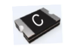
holding current and working voltage, and is suitable for wide range of application.
Features
■ High Operation Temperature ˗ -40℃~125℃ ■ Compact design saves board space ■ TUV/UL compliant ■ IATF/TS16949 certificated ■ Resettable solution against overcurrent and short-circuit
Applications
■ Actuators and medium motors ■ Industrial power supply
■ Fast response to fault current ■ Compatible with high-volume electronics assembly ■ AEC-Q200 qualified
■ Industrial motor driver ■ Powered outputs
■ Automotive ECU and current sensor etc. protection ■ Harness/junction box protection
Electrical Characteristics
| Part Number | I hold (A) | I trip (A) | V max (Vdc) | I max (A) | P d typ. (W) | Maximum Time To Trip | Resistance | ||
|---|---|---|---|---|---|---|---|---|---|
| Time (Sec.) | Current (A) | R min (Ω) | R 1max (Ω) | ||||||
| SMDH1206B005TF | 0.05 | 0.25 | 30 | 20 | 0.8 | 0.25 | 1.5 | 1.50 | 35.00 |
| SMDH1206B010TF | 0.10 | 0.35 | 30 | 10 | 0.8 | 0.1 | 1.0 | 0.70 | 10.0 |
| SMDH1206B012TF | 0.12 | 0.45 | 30 | 10 | 0.6 | 0.2 | 1.0 | 0.60 | 10.50 |
| SMDH1206B016TF | 0.16 | 0.80 | 30 | 20 | 0.9 | 0.1 | 8.0 | 0.60 | 6.00 |
| SMDH1206B020TF/24 | 0.20 | 0.70 | 24 | 10 | 0.6 | 0.6 | 1.0 | 0.50 | 5.60 |
| SMDH1206B020TF/30 | 0.20 | 0.70 | 30 | 60 | 0.6 | 0.6 | 1.0 | 0.50 | 5.60 |
| SMDH1206B025TF | 0.25 | 0.81 | 16 | 20 | 0.6 | 0.08 | 8.0 | 0.35 | 4.30 |
| SMDH1206B030TF | 0.30 | 0.82 | 24 | 10 | 1.0 | 0.1 | 8.0 | 0.10 | 1.95 |
| SMDH1206B035TF | 0.35 | 1.15 | 16 | 50 | 1.0 | 0.2 | 3.5 | 0.15 | 1.60 |
| SMDH1206B035TF/30 | 0.35 | 1.20 | 30 | 20 | 1.2 | 0.1 | 8.0 | 0.10 | 2.20 |
| SMDH1206B050TF | 0.50 | 2.50 | 24 | 20 | 1.7 | 0.1 | 8.0 | 0.10 | 1.60 |
| SMDH1206B075TF | 0.75 | 2.00 | 6 | 10 | 1.1 | 0.1 | 8.0 | 0.05 | 0.40 |
| SMDH1206B110TF | 1.10 | 5.20 | 6 | 100 | 0.6 | 0.1 | 8.0 | 0.03 | 0.45 |
| SMDH1206B125TF | 1.25 | 3.75 | 6 | 100 | 0.6 | 0.2 | 8.0 | 0.02 | 0.25 |
| SMDH1206B150TF | 1.50 | 4.50 | 6 | 100 | 0.6 | 0.3 | 8.0 | 0.01 | 0.30 |
| SMDH1206B175TF | 1.75 | 7.00 | 6 | 100 | 0.7 | 1.0 | 8.0 | 0.01 | 0.25 |
| SMDH1206B200TF | 2.00 | 6.00 | 6 | 100 | 0.7 | 1.0 | 8.0 | 0.01 | 0.25 |
Page 3

Note on Electrical Characteristics
■ Vocabulary
- Ihold = Hold current: maximum current device will pass without tripping in 23℃ still air.
- Itrip = Trip current: minimum current at which the device will trip in 23℃ still air.
- Vmax = Maximum voltage device can withstand without damage at rated current (Imax)
- Imax = Maximum fault current device can withstand without damage at rated voltage (Vmax)
- Pd typ. = Typical power dissipated from device when in the tripped state at 23℃ still air.
- Rmin = Minimum resistance of device in initial (un-soldered) state.
- R1max = Maximum resistance of device at 23℃ measured one hour after tripping or reflow soldering of 260℃ for 20 sec. ■ Value specified is determined by using the PWB with 0.030”\*1.5oz copper traces. ■ Caution: Operation beyond the specified rating may result in damage and possible arcing and flame. ■ Specifications are subject to change without notice.
Polymeric PTC Selecting Guide
■ Determine the following operating parameters for the circuits:
- Maximum interrupt current (Imax)
- Normal operating current (Ihold)
- Normal operating temperature surrounding device (min℃/max℃)
- Maximum circuit voltage (Vmax)
■ Select the device from factor and dimension suitable for the application ■ Compare the maximum rating for Vmax and Imax of the PPTC device with the circuit in application and make sure the circuit’s requirement does not exceed the device rating. ■ Check that PPTC device’s trip time (time-to-trip) will protect the circuit. ■ Verify that the circuit operating temperature is within the PPTC device’s normal operating temperature range. ■ Verify that performance and suitability of the chosen PPTC device in the application.
Page 4

WARNING
! ■ Mechanical Stress
- PPTC devices will undergo a thermal expansion during fault condition. If PPTC devices are installed or placed in an application where the space between PPTC devices and the surrounding materials (e.g., covering materials, packaging materials,encapsulate materials and the like) is insufficient, it will cause an inhibiting effect upon the thermal expansion. Pressing, twisting, bending and other kinds of mechanical stress will also adversely affect the performance of the PPTC devices, and shall not be used orapplied.
■ Chemical Pollutants
- Silicone-based oils, oils, solvents, gels, electrolytes, fuels, acids, and the like will adversely affect the properties of PPTC devices,
and shall not be used or applied. ■ Electronic and Thermal Effect
- PPTC devices are secondary protection devices and are used solely for sporadic, accidental over-current or over-temperature error condition, and shall NOT be used if or when constant or repeated fault conditions (such fault conditions may be causedby, among others, incorrect pin-connection of a connector) or over-extensive trip events may occur.
- PPTC devices are different from fuses and, when a fault condition occurs, will go into high-resistance state and do not open circuit, in which case the voltage at such PPTC devices may reach a hazardous level.
- Operation over the maximum rating or other forms of improper use may cause failure, arcing, flame and/or other damage to the PPTC devices.
- Conductive material contamination, such as metal particle, may induce shortage, flame or arcing.
- Due to the inductance, the operation circuits may generate a circuit voltage (Ldi/dt) above the rated voltage of PPTC devices, which shall not be used under such circumstances.
■ General
- Customers shall evaluate and test the properties of PPTC devices independently to verify and ensure that their individual applications will be met.
- The performance of PPTC devices will be adversely affected if they are improperly used under electronic, thermal and/or mechanical procedures and/or conditions non-conformant to those recommended by manufacturer.
- Customers shall be responsible for determining whether it is necessary to have back-up, failsafe and/or fool-proof protection To avoid or minimize damage that may result from extra-ordinary, irregular function or failure of PPTC devices.
- Any and all responsibilities and liabilities are disclaimed if any item under this notice of warning is not complied with.
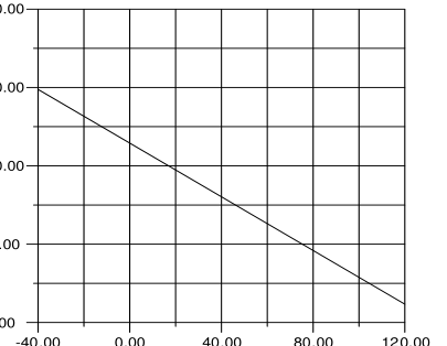
Thermal Derating Curve
200.00
150.00
100.00
50.00
0.00
Device Ambient Temperature (℃)
Page 5

Thermal Derating Chart Recommended Hold Current (A) at Ambient Temperature (℃)
| Part Number | Ambient Operation Temperature | |||||||||
|---|---|---|---|---|---|---|---|---|---|---|
| -40℃ | -20℃ | 0℃ | 25℃ | 40℃ | 50℃ | 60℃ | 70℃ | 85℃ | 125℃ | |
| SMDH1206B005TF | 0.074 | 0.066 | 0.058 | 0.05 | 0.043 | 0.038 | 0.035 | 0.030 | 0.028 | 0.01 |
| SMDH1206B010TF | 0.18 | 0.16 | 0.15 | 0.10 | 0.09 | 0.08 | 0.07 | 0.04 | 0.02 | 0.01 |
| SMDH1206B012TF | 0.18 | 0.16 | 0.14 | 0.12 | 0.10 | 0.09 | 0.08 | 0.04 | 0.02 | 0.01 |
| SMDH1206B016TF | 0.25 | 0.21 | 0.19 | 0.16 | 0.14 | 0.13 | 0.12 | 0.06 | 0.04 | 0.012 |
| SMDH1206B020TF/24 | 0.28 | 0.25 | 0.23 | 0.20 | 0.170 | 0.15 | 0.14 | 0.12 | 0.09 | 0.03 |
| SMDH1206B020TF/30 | 0.28 | 0.25 | 0.23 | 0.20 | 0.17 | 0.15 | 0.14 | 0.12 | 0.09 | 0.03 |
| SMDH1206B025TF | 0.37 | 0.33 | 0.29 | 0.25 | 0.22 | 0.20 | 0.17 | 0.15 | 0.10 | 0.03 |
| SMDH1206B030TF | 0.45 | 0.40 | 0.35 | 0.30 | 0.25 | 0.22 | 0.20 | 0.18 | 0.10 | 0.03 |
| SMDH1206B035TF | 0.54 | 0.48 | 0.43 | 0.35 | 0.32 | 0.29 | 0.26 | 0.24 | 0.20 | 0.08 |
| SMDH1206B035TF/30 | 0.51 | 0.46 | 0.41 | 0.35 | 0.31 | 0.29 | 0.26 | 0.24 | 0.20 | 0.08 |
| SMDH1206B050TF | 0.73 | 0.66 | 0.58 | 0.50 | 0.45 | 0.42 | 0.39 | 0.35 | 0.31 | 0.09 |
| SMDH1206B075TF | 1.07 | 0.98 | 0.90 | 0.75 | 0.70 | 0.66 | 0.61 | 0.56 | 0.50 | 0.06 |
| SMDH1206B110TF | 1.80 | 1.65 | 1.50 | 1.10 | 1.15 | 1.08 | 1.00 | 0.90 | 0.80 | 0.20 |
| SMDH1206B125TF | 1.90 | 1.68 | 1.51 | 1.25 | 1.15 | 1.08 | 1.00 | 0.90 | 0.80 | 0.20 |
| SMDH1206B150TF | 2.20 | 1.99 | 1.77 | 1.50 | 1.34 | 1.23 | 1.10 | 1.01 | 0.84 | 0.17 |
| SMDH1206B175TF | 2.50 | 2.25 | 2.00 | 1.75 | 1.55 | 1.45 | 1.35 | 1.25 | 0.92 | 0.15 |
| SMDH1206B200TF | 2.60 | 2.44 | 2.35 | 2.00 | 1.78 | 1.67 | 1.50 | 1.45 | 0.86 | 0.11 |
Average Time-Current Curve
A-SMDH1206B010TF
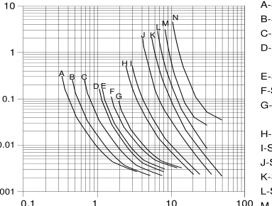
B-SMDH1210B012TF C-SMDH1206B016TF D-SMDH1206B020TF/24 SMDH1206B020TF/30 E-SMDH1206B025TF F-SMDH1206B030TF G-SMDH1206B035TF SMDH1206B035TF/30 H-SMDH1206B050TF I-SMDH1206B075TF J-SMDH1206B110TF K-SMDH1206B125TF L-SMDH1206B150TF
0.001
M-SMDH1206B175TF
Fault Current (A)
N-SMDH1206B200TF
Page 6

Soldering Parameters
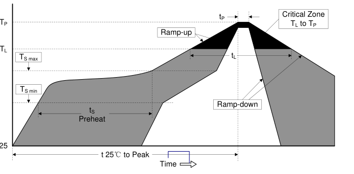
| Profile Feature | Pb-Free Assembly |
| Average ramp-up rate (T to T ) S max P | 3℃ /second max. |
| Preheat -Temperature Min (T ) S min -Temperature Max (T ) S max -Time (min to max) (T to T ) S min S max | 150℃ 200℃ 60-180 seconds |
| Time maintained above: -Temperature (T ) L -Time (t ) L | 217℃ 60-150 seconds |
| Peak Temperature (T ) P | 260℃ |
| Time within 5℃ of actual Peak Temperature (t ) P | 20-40 seconds |
| Ramp-down Rate | 6℃ /second max. |
| Time 25℃ to Peak Temperature | 8 minutes max. |
| Storage Condition | 0℃~35℃, ≤70%RH |
- Recommended reflow methods: IR, vapor phase oven, hot air oven, N2 environment for lead-free
- Recommended maximum paste thickness is 0.25mm (0.010 inch)
- Device can be cleaned using standard industry methods and solvents. Note 1: All temperature refer to topside of the package, measured on the package body surface. Note 2: If reflow temperatures exceed the recommended profile, devices may not meet the performance
requirements.
Page 7

Physical Dimensions (mm)
C
A
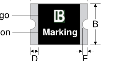
BK Logo
Part identification
| Part Number | A | B | C | D | E | |||||
|---|---|---|---|---|---|---|---|---|---|---|
| Min. | Max. | Min. | Max. | Min. | Max. | Min. | Max. | Min. | Max. | |
| SMDH1206B005TF | 3.00 | 3.40 | 1.50 | 1.80 | 0.40 | 1.00 | 0.25 | 0.75 | 0.05 | 0.45 |
| SMDH1206B010TF | 3.00 | 3.40 | 1.50 | 1.80 | 0.30 | 0.70 | 0.25 | 0.75 | 0.05 | 0.45 |
| SMDH1206B012TF | 3.00 | 3.40 | 1.50 | 1.80 | 0.40 | 1.00 | 0.25 | 0.75 | 0.05 | 0.45 |
| SMDH1206B016TF | 3.00 | 3.40 | 1.50 | 1.80 | 0.50 | 0.80 | 0.25 | 0.75 | 0.05 | 0.45 |
| SMDH1206B020TF/24 | 3.00 | 3.40 | 1.50 | 1.80 | 0.35 | 0.85 | 0.25 | 0.75 | 0.05 | 0.45 |
| SMDH1206B020TF/30 | 3.00 | 3.40 | 1.50 | 1.80 | 0.35 | 0.85 | 0.25 | 0.75 | 0.05 | 0.45 |
| SMDH1206B025TF | 3.00 | 3.40 | 1.50 | 1.80 | 0.35 | 0.85 | 0.25 | 0.75 | 0.05 | 0.45 |
| SMDH1206B030TF | 3.00 | 3.40 | 1.50 | 1.80 | 0.40 | 0.80 | 0.25 | 0.75 | 0.05 | 0.45 |
| SMDH1206B035TF | 3.00 | 3.40 | 1.50 | 1.80 | 0.40 | 0.80 | 0.25 | 0.75 | 0.05 | 0.45 |
| SMDH1206B035TF/30 | 3.00 | 3.40 | 1.50 | 1.80 | 0.80 | 1.30 | 0.25 | 0.75 | 0.05 | 0.45 |
| SMDH1206B050TF | 3.00 | 3.40 | 1.50 | 1.80 | 0.60 | 1.00 | 0.25 | 0.75 | 0.05 | 0.45 |
| SMDH1206B075TF | 3.00 | 3.40 | 1.50 | 1.80 | 0.60 | 1.00 | 0.25 | 0.75 | 0.05 | 0.45 |
| SMDH1206B110TF | 3.00 | 3.40 | 1.50 | 1.80 | 0.65 | 1.15 | 0.25 | 0.75 | 0.05 | 0.45 |
| SMDH1206B125TF | 3.00 | 3.40 | 1.50 | 1.80 | 0.70 | 1.20 | 0.25 | 0.75 | 0.05 | 0.45 |
| SMDH1206B150TF | 3.00 | 3.40 | 1.50 | 1.80 | 0.85 | 1.65 | 0.25 | 0.75 | 0.05 | 0.45 |
| SMDH1206B175TF | 3.00 | 3.40 | 1.50 | 1.80 | 0.85 | 1.80 | 0.25 | 0.75 | 0.05 | 0.45 |
| SMDH1206B200TF | 3.00 | 3.40 | 1.50 | 1.80 | 0.85 | 1.80 | 0.25 | 0.75 | 0.05 | 0.45 |
Recommended Pad Layout (mm)
1.80typ.
1.00typ.
1.00typ.
Page 8

Environmental Specifications
| Operating / Storage temperature | -40℃ to +125℃ |
| Maximum Device Surface Temperature in Tripped State | 175℃ |
| Passive Aging | +125℃, 1000 hours ±50% typical resistance change |
| Humidity Aging | +85℃, 85%R.H. 1000 hours ±50% typical resistance change |
| Thermal Shock | MIL-STD-202, Method 107G +125℃/-40℃ 20 times -50% typical resistance change |
| Solvent Resistance | MIL-STD-202, Method 215 No change |
| Vibration | MIL-STD-883C, Method 2007.1, Condition A No change |
| Moisture Level Sensitivity | Level 1, J-STD-020C |
Packaging Quantity and Marking
| Part Number | Marking | Quantity | Part Number | Marking | Quantity |
|---|---|---|---|---|---|
| SMDH0805B005TF | A | 4000 | SMDH1206B025TF | HD | 4000 |
| SMDH0805B010TF | C | 4000 | SMDH1206B030TF | H3 | 4000 |
| SMDH0805B016TF | B | 4000 | SMDH1206B035TF | 35 | 4000 |
| SMDH0805B020TF | D | 4000 | SMDH1206B035TF/30 | V | 3000 |
| SMDH0805B035TF | E | 3000 | SMDH1206B050TF | 50 | 4000 |
| SMDH0805B050TF | G | 3000 | SMDH1206B075TF | H7 | 4000 |
| SMDH1206B005TF | H0 | 3000 | SMDH1206B110TF | HC | 4000 |
| SMDH1206B010TF | 10 | 4000 | SMDH1206B125TF | HB | 3000 |
| SMDH1206B012TF | H1 | 4000 | SMDH1206B150TF | H5 | 2000 |
| SMDH1206B016TF | 16 | 4000 | SMDH1206B175TF | HG | 2000 |
| SMDH1206B020TF/24 | H2 | 4000 | SMDH1206B200TF | H2 | 2000 |
| SMDH1206B020TF/30 | HA | 4000 | / | / | / |
◎ 12mm tape on 7 inch reel per EIA-481 (equivalent to IEC286, part 3)
Physical Specifications
| Terminal Material | Solder-Plated Copper (Solder Material: Matte Tin (Sn)) |
|---|---|
| Plating Thickness | Sn:≥15μm ,Cu:≥20μm |
| Lead Solderability | Meets EIA Specification RS186-9E, ANSI/J-STD-002 Category 3. |
Page 9

Packaging
| Tape | Symbol | Dimensions (mm) | ||
| H1206B010TF H1206B012TF H1206B016TF H1206B020TF/24 H1206B020TF/30 H1206B025TF H1206B030TF H1206B035TF H1206B110TF | H1206B005TF H1206B035TF/30 H1206B050TF H1206B075TF H1206B125TF | H1206B150TF H1206B175TF H1206B200TF | ||
| W | 8.00±0.30 | 8.00±0.30 | 8.00±0.30 | |
| F | 3.50±0.05 | 3.50±0.05 | 3.50±0.05 | |
| E | 1.75±0.10 | 1.75±0.10 | 1.75±0.10 | |
| D0 | 1.55±0.05 | 1.55±0.05 | 1.55±0.05 | |
| D1 | 1.00±0.10 | 1.00±0.10 | 1.00±0.10 | |
| P0 | 4.00±0.10 | 4.00±0.10 | 4.00±0.10 | |
| P1 | 4.00±0.10 | 4.00±0.10 | 4.00±0.10 | |
| P2 | 2.00±0.05 | 2.00±0.05 | 2.00±0.05 | |
| A0 | 1.95±0.10 | 1.92±0.10 | 1.92±0.10 | |
| B0 | 3.65±0.10 | 3.65±0.10 | 3.65±0.10 | |
| T | 0.20±0.10 | 0.20±0.10 | 0.20±0.10 | |
| K0 | 0.87±0.10 | 1.30±0.10 | 1.70±0.10 | |
| Leader min. | 390 | |||
| Trailer min. | 160 | |||
| Reel | C | Φ178.0±1.0 | ||
| D | Φ60.2±0.5 | |||
| H | 11.0±0.5 | |||
| W | 9.0±1.5 | |||
Page 10

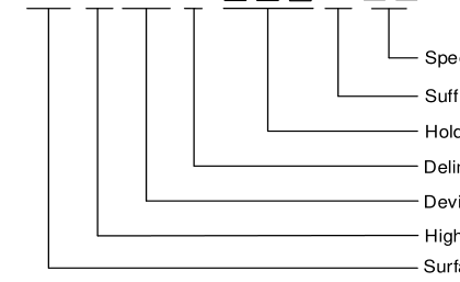
Part Number System
TF
SMD H 1206 B
LEGAL DISCLAIMER
Speclal Voltage Rating(Optional)
Suffix symbol (meaningless)
Holding Current Rating
Delimiter
Device Dimensions: Length/Width (Unit: 1/100 inch)
High Temperature Surface Mount Device
YAGEO, its distributors and agents (collectively, “YAGEO”), hereby disclaims any and all liabilities for any errors, inaccuracies or incompleteness contained in any product related information, including but not limited to product specifications, datasheets, pictures and/or graphics. YAGEO may make changes, modifications and/or improvements to product related information at any time and without notice.
YAGEO makes no representation, warranty, and/or guarantee about the fitness of its products for any particular purpose or the continuing production of any of its products. To the maximum extent permitted by law, YAGEO disclaims (i) any and all liability arising out of the application or use of any YAGEO product, (ii) any and all liability, including without limitation special, consequential or incidental damages, and (iii) any and all implied warranties, including warranties of fitness for a particular purpose, non -infringement and merchantability.
YAGEO products are designed for general purpose applications under normal operation and usage conditions. Please contact YAGEO for the applications listed below which require especially high reliability for the prevention of defects which might directly cause damage to the third party's life, body or property: Aerospace equipment (artificial satellite, rocket, etc.), Atomic energy-related equipment, Aviation equipment, Disaster prevention equipment, crime prevention equipment, Electric heating apparatus, burning equipment, Highly public information network equipment, data-processing equipment , Medical devices, Military equipment, Power generation control equipment, Safety equipment, Traffic signal equipment, Transportation equipment and
Undersea equipment, or for any other application or use in which the failure of YAGEO products could result in personal injury or death, or serious property damage. Particularly YAGEO Corporation and its affiliates do not recommend the use of commercial or automotive grade products for high reliability applications or manned space flight.
Information provided here is intended to indicate product specifications only. YAGEO reserves all the rights for revising this content without further notification, as long as products are unchanged. Any product change will be announced by PCN.