
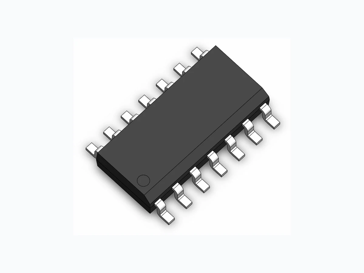
SMDA05C-8 SOCAY
Document overview
- Manufacturer or author: Provided By www.digicamel.com(FREE DATASHEET DOWNLOAD SITE)
- PDF pages: 3
Technical content
Transient Voltage Suppressors Array for ESD Protection Revision January 06, 2014 1 / 3 @ SOCAY Electronics Co., Ltd. 2014 Specifications are subject to change without notice. Please refer to www.socay.com for current information. SMDAXXC-8 Series SOCAY Electronics Co., Ltd. www.socay.com SOP-14 The SMDAxxC-8 series of transient voltage suppressors are designed to protect components which are connected to data and transmission lines from voltage surges caused by electrostatic discharge (ESD), electrical fast transients (EFT), and lightning. TVS diodes are characterized by their high surge capability, low operating and clamping voltages, and fast response time. This makes them ideal for use as board level protection of sensitive semiconductor components. The SMDAxxC-8 is designed to provide transient suppression on multiple data lines and I/O ports. The low profile SOP-14 design allows the user to protect up to eight data and I/O lines with one package. They are bidirectional device and may be used on lines where the normal operating voltage is above and below ground (i.e. -12V to +12V). u 300 Watts Peak Pulse Power per Line (tp=8/20 μs) u Protects Eight Data Lines u Working Voltage : 5V, 12V, 15V and 24V u Monolithic Design u RoHS Compliant u IEC61000-4-2 (ESD) ±30kV (air), ±30kV (contact) - 5V, 12V, 15V u IEC61000-4-2 (ESD) ±15kV (air), ±8kV (contact) -24V u IEC61000-4-4 (EFT) 40A (5/50 ηs) u IEC61000-4-5 (Lightning) 12A (8/20 μs) u Microprocessor Based Equipment u RS-232 and RS-422 Data Lines u LAN/WAN Equipment u Notebooks, Desktops and Servers u Instrumentation u Set Top Box u Serial and Parallel Ports u Peripherals u JEDEC SOP-14 Package u Molding Compound Flammability Rating : UL 94V-0 u Weight 150.0 Milligrams (Approximate) u Quantity Per Reel : 500pcs u Reel Size : 7 inch u Lead Finish : Lead Free Symbol Parameter Value Units PPP Peak Pulse Power (tp=8/20μs waveform) 300 W TL Lead Soldering Temperature 260 (10sec) ºC TSTG Storage Temperature Range -55 to +150 ºC TJ Operating Temperature Range -55 to +150 ºC IEC61000-4-4 (EFT) 40 A IEC61000-4-5 ( Lightning ) 12 A Mechanical Characteristics
Description
Applications
Mechanical Characteristics
Transient Voltage Suppressors Array for ESD Protection Revision January 06, 2014 2 / 3 @ SOCAY Electronics Co., Ltd. 2014 Specifications are subject to change without notice. Please refer to www.socay.com for current information. SMDAXXC-8 Series SOCAY Electronics Co., Ltd. www.socay.com VC Part Number Device Marking VRWM (V) (Max.) VB (V) (Min.) IT (mA) VC @5A (Max.) (Max.) (@A) IR (μA) (Max.) C (pF) (Typ.) SMDA05C-8 SMDA05C-8 5.0 6.0 1 9.8 19.0 30 20 350 SMDA12C-8 SMDA12C-8 12.0 13.3 1 19.0 29.2 20 1 120 SMDA15C-8 SMDA15C-8 15.0 16.7 1 24.0 31.1 18 1 75 SMDA24C-8 SMDA24C-8 24.0 26.7 1 43.0 45 13 1 50 Fig1. 8/20 μs Pulse Waveform Fig2. ESD Pulse Waveform (according to IEC 61000-4-2) Fig3. Non - Repetitive Peak Pulse Power vs. Pulse Time Electrical Characteristics (@ 25℃ Unless Otherwise Specified ) Characteristic Curves 0 5 10 15 20 25 30 120 tr 100 Peak Value IPP td=t IPP/2 TEST WAVEFORM PARAMETERS tr=8μs td=20μs t - Time (μs) IPP - Peak Pulse Current - % of IPP 60ns 10% Percent of Peak Pulse Current % 30ns tr = 0.7~1ns Time (ns) 90% 100% Pulse Duration - tp (μs) Peak Pulse Power - PPK (kW) 0.01 0.1 0.1 1 10 100 1000
Transient Voltage Suppressors Array for ESD Protection Revision January 06, 2014 3 / 3 @ SOCAY Electronics Co., Ltd. 2014 Specifications are subject to change without notice. Please refer to www.socay.com for current information. SMDAXXC-8 Series SOCAY Electronics Co., Ltd. www.socay.com Fig4. ESD Clamping (+8KV Contac per IEC61000-4-2) Fig5. ESD Clamping (-8KV Contac per IEC61000-4-2) Millimeters Inches Symbol Min. Max. Min. Max. A 8.55 8.75 0.337 0.344 B 3.80 4.00 0.150 0.157 C 1.35 1.75 0.054 0.068 D 0.35 0.49 0.014 0.019 F 0.40 1.25 0.016 0.049 G 1.27 BSC 0.050 BSC J 0.19 0.25 0.008 0.009 K 0.10 0.25 0.004 0.009 M 0° 7° 0° 7° P 5.80 6.20 0.228 0.244 R 0.25 0.50 0.010 0.019 Symbol Inches Millimeters C (0.205) (5.20) G 0.118 3.00 P 0.050 1.27 X 0.024 0.60 Y 0.087 2.20 Z 0.291 7.40 Soldering Footprint Characteristic Curves