
SM712 LEIDITECH
Document overview
- Manufacturer or author: Provided By www.digicamel.com(FREE DATASHEET DOWNLOAD SITE)
- PDF pages: 3
Technical content
Features
Ultra low leakage: nA level Operating voltage: 7Vor12V Low clamping voltage Complies with following standards: – IEC 61000-4-2 (ESD) immunity test Air discharge: ±30kV Contact discharge: ±30kV – IEC61000-4-4 (EFT) 40A (5/50ns) – IEC61000-4-5 (Lightning) 12A (8/20μs) RoHS Compliant
Applications
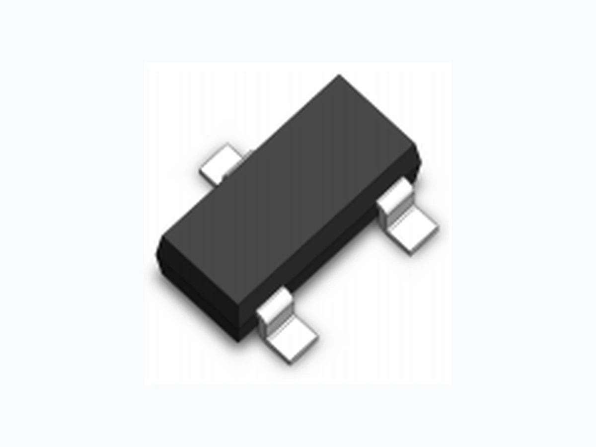
USB 2.0 power and data line Set-top box and digital TV Digital video interface (DVI) Notebook Computers SIM Ports 10/100 Ethernet Dimensions SOT-23 Pin Configuration Mechanical Characteristics Package: SOT-23 Lead Finish: Lead Free UL Flammability Classification Rating 94V-0 Quantity Per Reel:3,000pcs Reel Size:7 inch Rev : 01.06.2014 1/3 www.leiditech.com Absolute Maximum Ratings (Tamb=25°C unless otherwise specified) Parameter Symbol Value Unit Peak Pulse Power (8/20µs) Ppp 400 W ESD per IEC 61000−4−2 (Air) V ESD ± 30 Kv ESD per IEC 61000−4−2 (Contact) ± 30 Operating Temperature Range T J -55 to +125 Storage Temperature Range T STJ -55 to +150
Fig1. 8/20µs Pulse Waveform 0 5 10 15 20 25 30 120 t r 100 Peak Value I PP t d =t I PP TEST WAVEFORM PARAMETERS t r s t d =20 s t - Time ( I PP - Peak Pulse Current - % of I PP Fig3. Power Derating Curve 0 25 50 75 100 125 150 110 100 % of Rated Power A mbient Temperature T A º Fig2. ESD Pulse Waveform (according to IEC 61000-4-2) 60ns 10% Percent of Peak Pulse Current % 30ns tr = 0.7~1ns Time (ns) 90% 100% Rev : 01.06.2014 2/3 www.leiditech.com SM712
Electrical Characteristics
(TA=25°C unless otherwise specified) Part Number Device Marking V RWM (V) V BR (V) I T (mA) V C @1A Vc I R μA (Max) C (Pf) (Typ.) (Max) (@A) SM712 Pin 3 to Pin 1/Pin 2 7 7.5 1 10 12 17 10 45 Pin 1 / Pin 2 to Pin 2 12 13.3 1 20 26 17 1 45 712
Shanghai Leiditech Electronic Co.,Ltd Email: sale1@leiditech.com Tel : +86- 021 50828806 Fax : +86- 021 50477059 Rev : 01.06.2014 3/3 www.leiditech.com SM712 Millimeters Inches Symbol Min. Nom. Max. Min. Nom. Max. 0.01 0.06 0.10 0.001 0.002 0.004 c 0.09 0.13 0.18 0.003 0.005 0.007 E 1.20 1.30 1.40 0.047 0.051 0.055 L 0.35 0.54 0.69 0.014 0.021 0.029 Symbol Millimeters Inches X 0.80 0.031 0.95 0.037 Y 0.90 0.035 Z 2.00 0.079 Soldering Footprint