
DATASHEET SEARCH SITE
Document overview
- Manufacturer or author: Provided By www.digicamel.com(FREE DATASHEET DOWNLOAD SITE)
- PDF pages: 5
Technical content
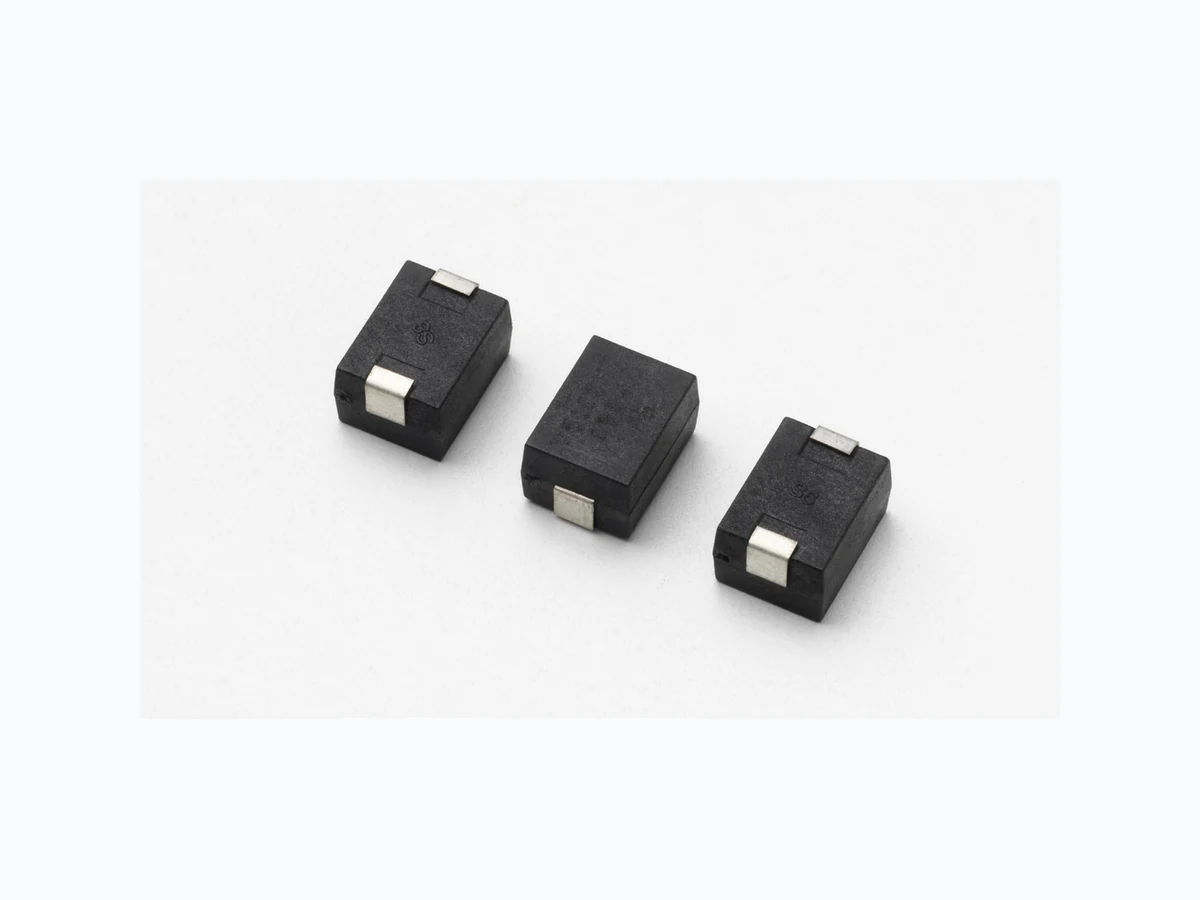
Features
- Electrical equivalent to leaded types LA/ZA series
- AC Voltage Rating 50 to 510VAC rms
- No De-Rating up to 85°C ambient
- Good solderability
- Available in tape and reel
- Application of AC power meters
- Lead free and RoHS compliant Agency Approvals Absolute Maximum Ratings
- For ratings of individual members of a series, see Device Ratings and Specifications chart Continuous SM7 Series Units Steady State Applied Voltage: AC Voltage Range (VM(AC)RMS) 50 to 510 V DC Voltage Range (VM(DC)) 68 to 675 V Transients: Peak Pulse Current (ITM) For 8/20µs Current Wave (See Figure 2) 1200 A Single Pulse Energy Range For 10/1000µs Current Wave (WTM) 10 to 40 J Operating Ambient Temperature Range (TA) -40 to +85 OC Storage Temperature Range (TSTG) -55 to +125 OC Temperature Coefficient (aV) of Clamping Voltage (VC) at Specified Test Current <0.01 %/OC Hi-Pot Encapsulation (COATING Isolation Voltage Capability) (Dielectric must withstand indicated DC voltage for one minute per MIL -STD 202, Method 301) 2500 V COATING Insulation Resistance 1000 MΩ CAUTION: Stresses above those listed in “Absolute Maximum Ratings” may cause permanent damage to the device. This is a stress only rating and operation of the device at these or any other conditions above those indicated in the operational sections of this specification is not implied. SM7 Varistor Series Agency Agency Approval Agency File Number UL1449 E320116 Additional Information Datasheet SamplesResources
© 2017 Littelfuse, Inc. Specifications are subject to change without notice. Revised: 09/14/17 Metal-Oxide Varistors (MOVs) Surface Mount Varistors > SM7 Series SM7 Series Ratings & Specifications Maximum Rating (85°C) Specifications (25°C) Continuous Transient Varistor Voltage at 1mA DC Test Current Maximum Clamping Voltage 8 x 20 µs Typical Capacitance f = 1MHzVRMS VDC Energy 10 x 1000µs Peak Current 8 x 20µs Part Number VM(AC) VM(DC) WTM ITM VNOM Min VNOM Max VC IPK C (V) (V) (J) (A) (V) (V) (V) (A) (pF) V50SM7 50 68 4 1200 73 91 135 10 700 V60SM7 60 81 5 1200 90 110 165 10 600 V115SM7 115 153 10 1200 162 198 300 10 200 V130SM7 130 175 11 1200 184 228 340 10 180 V140SM7 140 180 12 1200 198 242 360 10 160 V150SM7 150 200 13 1200 212 268 395 10 150 V175SM7 175 225 15 1200 247 303 455 10 130 V230SM7 230 300 20 1200 324 396 595 10 100 V250SM7 250 330 21 1200 354 429 650 10 90 V275SM7 275 369 23 1200 389 473 710 10 80 V300SM7 300 405 25 1200 420 517 775 10 70 V320SM7 320 420 25 1200 462 565 850 10 65 V385SM7 385 505 27 1200 558 682 1025 10 60 V420SM7 420 560 30 1200 610 74 8 1120 10 55 V460SM7 460 615 37 1200 640 790 1190 10 55 V480SM7 480 640 35 1200 670 825 1240 10 50 V510SM7 510 675 40 1200 735 910 1200 10 45 Part Numbering System For “VARISTOR” VM(AC) (Three digits -- 115V to 510V) V 275 SM7 SM7 SERIES All dimensions shown in milimeters 3.0±0.31.5±0.3 0.3 max 6.5 13.1 3.5 Soldering Pad Layout 1 1.4±0.3 8.3±0.3 3.6+/-0.3 for V50SM7-V60SM7 6.0+/-0.3 for V1 15SM7 to V510SM7 Product Dimensions
Specifications are subject to change without notice. and Wave soldering. Typical profiles are shown on the right. Wave soldering is the most strenuous of the processes. process should be rigidly controlled. peak temperature is essential to minimize thermal shock. to less than 50ºC before cleaning. soldering, the Wave Solder Profile still applies. considerably from site to site. FIGURE 14. REFLOW SOLDER PROFILE FIGURE 16. LEAD-FREE RE-FLOW SOLDER PROFILE
20 SECONDS MAXIMUM
FIGURE 14. REFLOW SOLDER PROFILE FIGURE 16. LEAD-FREE RE-FLOW SOLDER PROFILE FIGURE 14. REFLOW SOLDER PROFILE FIGURE 16. LEAD-FREE RE-FLOW SOLDER PROFILE
Specifications are subject to change without notice. the device from continuing to function, and to provide ample protection. FIGURE 1. CURRENT, ENERGY AND POWER DERATING test each product selected for their own applications. Littelfuse products are not designed for, and may not be used in, all applications. Read complete Disclaimer Notice at www.littelfuse.com/disclaimer-electronics.
© 2017 Littelfuse, Inc. Specifications are subject to change without notice. Revised: 09/14/17 Metal-Oxide Varistors (MOVs) Surface Mount Varistors > SM7 Series T ape & Reel Specifications for V50SM7 amd V60SM7 mm W 16.00±0.30 T 0.40±0.05 A0 11 .80±0.10 B0 8.60±0.10 K0 4.80±0.10 E 1 .75±0.10 F 7 .50±0.10 P0 4.00±0.10 P1 16.00±0.10 P2 2.00±0.10 D0 ø1 .50 +0.10/-0 D1 ø1 .50 +0.10/-0 A-A B-B 11.30 3.60 T 120° Ø21±0.8 2±0.5Ø1 3±0.2 DETAIL H DETAIL H Ø330 Ø100 16.5 21.5±0.4 Plastic Reel Carrier Tape 3.8 - 4.0mm 15° F E W P1D0 D1B A BA T ape & Reel Specifications for V115SM7 to V510SM7 mm W 16.00±0.30 T 0.40±0.05 A0 11 .80±0.10 B0 8.60±0.10 K0 6.80±0.10 E 1 .75±0.10 F 7 .50±0.10 P0 4.00±0.10 P1 16.00±0.10 P2 2.00±0.10 D0 ø1 .50 +0.10/-0 D1 ø1 .50 +0.10/-0 NOTES: 1) All dimensions per EIA-481-c 2) 10 pitches cumulative tolerance on tape ±0.20mm 3) Quantity per 13 inch (330 mm) reel: 600 pcs A-A B-B 11.30 3.60 T 120° Ø21±0.8 2±0.5Ø1 3±0.2 DETAIL H DETAIL H Ø330 Ø100 16.5 21.5±0.4 Plastic Reel Carrier Tape 6.2 10° F E W P1D0 D1B A BA NOTES: 1) All dimensions per EIA-481-c 2) 10 pitches cumulative tolerance on tape ±0.20mm 3) Quantity per 13 inch (330 mm) reel: 600 pcs