
SM5S LEIDITECH
Document overview
- Manufacturer or author: Provided By www.digicamel.com(FREE DATASHEET DOWNLOAD SITE)
- PDF pages: 6
Technical content
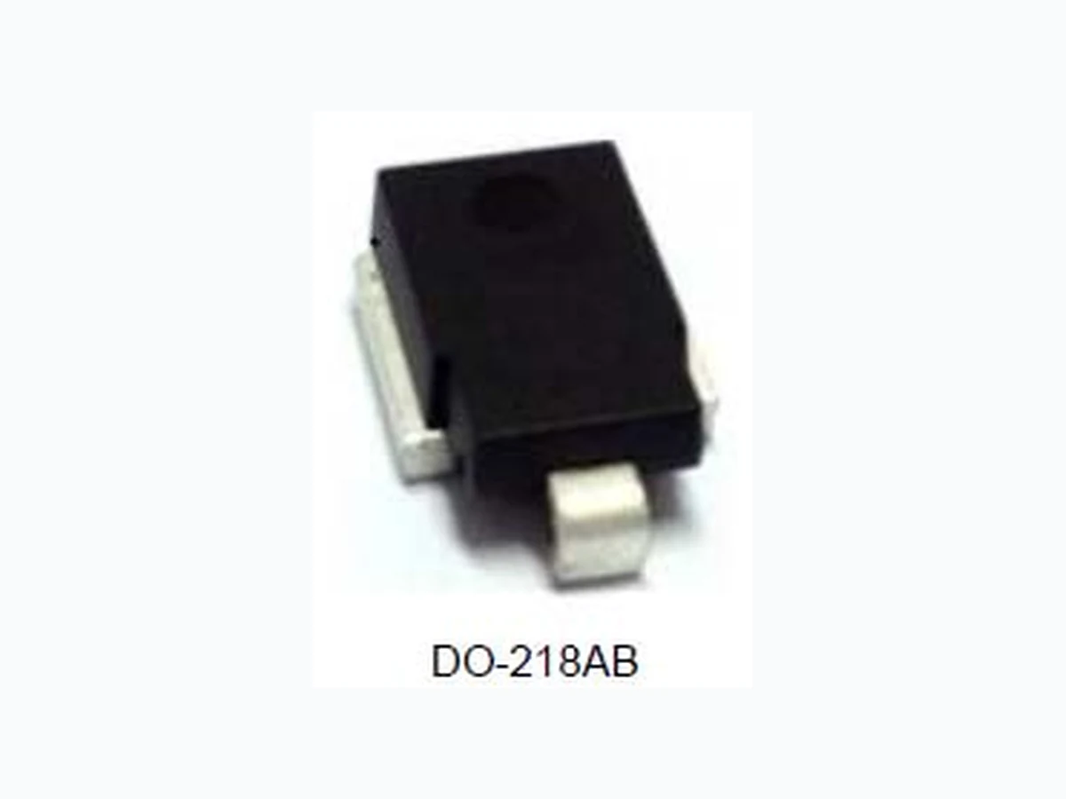
SM5S Series 3600W Transient Voltage Suppressor DESCRIPTION: SM5S Series TVS diodes can be used in sensitive electronics protection against voltage transients induced by inductive load switching and lighting, especially for automotive load dump protection application. FEATURES: Available in uni/bi-directional polarity. Low forward voltage drop & Low leakage current. High surge capability. Junction passivation optimized design passivated anisotropic rectifier technology. T J = 175 ℃ capability suitable for high reliability and automotive requirement. Meets ISO7637-2 surge specification (varied by test condition). Meets MSL level 1, per J-STD-020, LF maximum peak of 245℃. AEC-Q101 qualified. Compliant to ROHS Directive 2002/95/EC and in accordance to WEEE 2002/96/EC ABSOLUTE MAXIMUM RATINGS A =25ºC, RH=45%-75%, unless otherwise noted) Parameter Symbol Value Unit Peak pulse power dissipation on 10/1000us waveform P pp 3600 Watts Peak pulse power dissipation on 10/10000us waveform 2800 Watts Peak pulse current with 10/1000us waveform I pp See next table Amps Power dissipation on infinite heat Sink at T C =25℃ P D 5.0 Watts Peak forward surge current, 8.3ms single half sine-wave I FSM 500 Amps Operating Junction and Storage Temperature Range T J STG -55 to +150 Typical thermal resistance, junction to case R θJC 1.0 ℃/Watt DO-218AB Rev : www.leiditech.com 01.06.2014
ELECTRICAL CHARACTERISTICS
V R I R R V BR I T I T Vc @I pp I pp Uni-polar Bi-polar V μA@25 μA@175 min(V) max (V) mA V A Note: ① For all types maximum VF = 2.0 V at IF = 100 A measured on 8.3 ms single half sine-wave or equivalent square wave, duty cycle = 4 pulses per minute maximum. ②. Surge waveform: 10/1000μs V R :Stand-off Voltage -- Maximum voltage that can be applied V BR :Breakdown Voltage V C : Clamping Voltage -- Peak voltage measured across the suppressor at a specified Ipp I R : Reverse Leakage Current I T : Test current Mechanical Data CASE: DO-218AB Molding compound meets UL 94V-0 flammability rating Base P/NHE3-ROHS-compliant, AEC-Q101 qualified. Terminals: Matte tin plated leads, solder able per J-STD-002 and JESD 22-B102, HE3 suffix meets JESD 201 class 2 whisker tests. Rev : www.leiditech.com 01.06.2014 SM5S Series 3600W Transient Voltage Suppressor
ORDERING INFORMATION
RATINGS AND CHARACTERISTICS CURVES A =25ºC, unless otherwise noted) FIG.1: Power Derating Curve FIG.3: Load Dump Power Characteristics (10ms Exponential Wavaform) FIG.2: Pulse Waveform FIG.4: Reverse Power Capability Input Peak Pulse Current(%) Power Dissipation(W) 100 150 200 t-Time (ms) 100 125 150 175 2.0 6.0 8.0 4.0 2000 3000 Case Temperature ( ) tr=10μs td Peak Value I PPM Half Value- I PPM Ipp Tj=25 Pulse Width (td) is Defined as the Point Where the Peak Current Decays to 50% of I PPM 150 100 2500 1500 1000 500 Case Temperature ( ) Load Dump Power (W) 1000 10000 10 100 Pulse Width(ms)- I PP Exponential Waveform Reverse Surge Power(W) Rev : www.leiditech.com 01.06.2014 SM5S Series 3600W Transient Voltage Suppressor
0.01 0.1 1.0 100 Transient Thermal Impedance( /W) 0.01 0.1 FIG.5: Typical Transient Th e r m a l I m p e d a n c e t-Pulse Width SOLDERING PARAMETERS Reflow Condition Pre Heat -Temperature Min (T s(mi -Temperature Max(T s(m ax) -Time (Min to Max) (ts) Average ramp up rate (Liquid us Temp L ) to peak) T s(max) to T L - Ramp-up Rate Reflow -Temperature(T L )(Liqui d us) -Temperature(t L Peak Temp (T p Time within 5℃ of actual Peak Te mp (t Ramp-down Rate Time 25℃ to Peak Temp (T P Do not exceed 10 100 R θJA R θJC T y p i c a l T r a n s i e n t T h e rmal Impedance Pb-Free assembly (see FIG.5) s(min ) +150℃ s(ma ) +200℃ 60-180 secs. (Liquid us Te mp 3℃/sec. Max 3℃/sec. Max )(Liquid us) +217℃ 60-150 secs. +260(+0/-5)℃ of actual Peak Tem p (t p ) 30 secs. Max 6℃/sec. Max 8 min. Max +260℃ FIG.6: Reflo w condition Temperature T S(min) T S(max) T L T P time to pe ak temperatue (t 25 to peak) Pr eheat t s Reflow condition tp t L time to pea k temperatue Time (t 25 to peak) Ramp-up Ramp-down Pre heat Critical Zone T L to T P Rev : www.leiditech.com 01.06.2014 SM5S Series 3600W Transient Voltage Suppressor
TAPE AND REEL SPECIFICATION-DO-218AB ITEM W A0 B0 K0 K1 P1 E F D D1 P0 P2 T DIM TOL Note: 1. 10 pocket holes pitch cumulative tolerance ±0.20mm. 2. Carrier camber is 1mm in 100mm. 3. A0 and B0 are measured on a plane 0.30mm above the bottom of the pocket. 4. K0 is measured from a plane on the inside bottom of the pocket to the top surface of the pocket. 5. All dimensions meet EIA-481-2-A requirements. 6. Packing length per 22" Reel: 205Meters. Dimension Inches Millimeters Min Max Min Max A 0.374 0.413 9.5 10.5 B 0.327 0.342 8.3 8.7 C 0.524 0.539 13.3 13.7 D 0.592 0.628 15.0 16.0 E 0.335 0.358 8.5 9.1 F 0.374 0.398 9.5 10.1 G 0.094 0.118 2.4 3.0 H 0.020 0.028 0.5 0.7 J 0.106 0.146 2.7 3.7 K 0.075 0.083 1.9 2.1 L 0.185 0.201 4.7 5.1 Rev : www.leiditech.com 01.06.2014 SM5S Series 3600W Transient Voltage Suppressor
E L (PC S TAPING Dimension s D R E E L P C S PER CARTON (PCS) 3000 D i m e n s i o n s millimeters inches 330±0.2 13.0±0.008 24±0.2 0.94±0.008 REEL DIAMETERS (mm) 330 Shanghai Leiditech Electronic Co.,Ltd Email: sale1@leiditech.com Tel : +86- 021 50828806 Fax : +86- 021 50477059 Rev : www.leiditech.com 01.06.2014 SM5S Series 3600W Transient Voltage Suppressor