
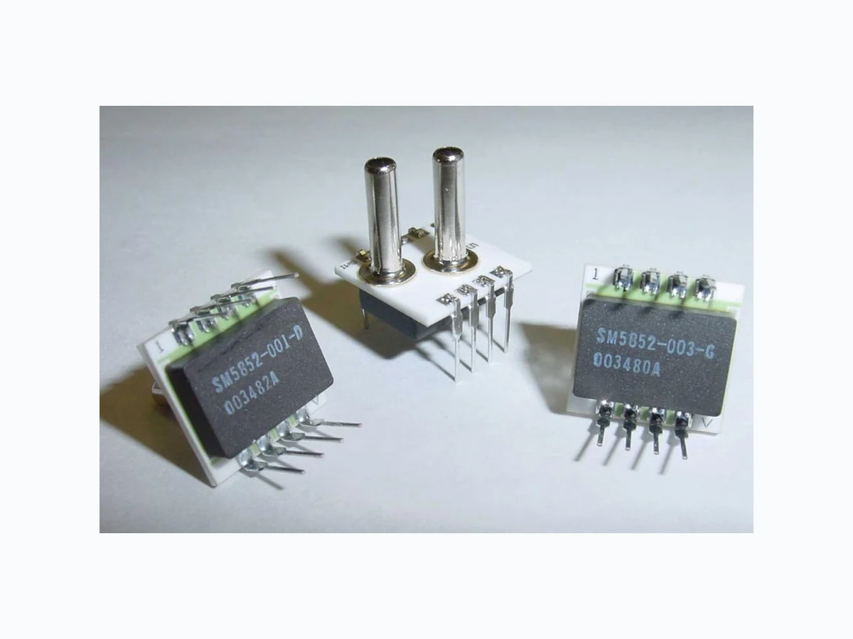
SM5812 ETC2
Document overview
- Manufacturer or author: Provided By www.digicamel.com(FREE DATASHEET DOWNLOAD SITE)
- PDF pages: 4
Technical content
2005 SMI Silicon Microstructures, Inc. ♦ 1701 McCarthy Blvd. ♦ Milpitas, CA 95035 ♦ USA Tel: 408-577-0100 ♦ Fax: 408-577-0123 ♦ Sales@si-micro.com ♦ www.si-micro.com Rev 1.4 6_05
- NOW WITH ACCESS TO DIGITAL TEMPERATURE AND CORRECTED DIGITAL PRESSURE
- LOW-COST, FULLY AMPLIFIED, CALIBRATED, AND COMPENSATED IN A SINGLE PACKAGE
- AVAILABLE FOR DIFFERENTIAL, SINGLE-ENDED DIFFERENTIAL, GAGE & ABSOLUTE APPLICATIONS
- MULTIPLE PRESSURE RANGES AVAILABLE TO MEASURE PRESSURE DOWN TO 0.15 PSI FULL-SCALE AND UP TO 100 PSI FULL-SCALE
DESCRIPTION
The Silicon Microstructures SM5812 and SM5852 series of OEM pressure sensors combines state-of-the-art pressure sensor technology with CMOS digital signal processing technology to produce an amplified, fully conditioned, multi-order pressure and temperature compensated sensor in a dual in-line package (DIP) configuration. Combining the pressure sensor with a custom signal conditioning ASIC in a single package simplifies the use of advanced silicon micromachined pressure sensors. Now, the pressure sensor can be mounted directly to a standard printed circuit board and an amplified, high level, calibrated pressure signal can be acquired from the digital interface or analog output. This eliminates the need of additional circuitry, such as a compensation network or micro- controller containing a custom correction algorithm. The SM5812/SM5852 Series pressure sensors are based on SMI's highly stable, piezoresistive pressure sensor chips mounted on a ceramic substrate. An electronically programmable ASIC is contained in the same package to provide calibration and temperature compensation. The model SM5812 is designed for operating pressure ranges from 0-5 PSI up to 0-100 PSI. The model SM5852 is designed for operating pressure ranges from 0-0.15 PSI up to 0-3 PSI. For both models, the sensor output is ratiometric with the supply voltage.
FEATURES
- Amplified, calibrated, fully signal conditioned output span of 4.0 VDC FS (0.5 to 4.5 V signal)
- Digital temperature and calibrated pressure available through I2C interface
- Output ratiometric with supply voltage
- Multi-order correction for pressure non- linearity (factory programmed)
- Multi-order correction for temperature coefficient of span and offset (factory programmed)
- Gage, differential, and absolute versions
- SMI’s unique low-pressure die allows for a full-scale pressure range of 0-0.15 PSI TYPICAL APPLICATIONS
- Barometric measurement
- Medical instrumentation
- Pneumatic control
- Gas flow
- Respirators and ventilators
- Heating, Ventilation and Air Conditioning (HVAC)
2005 SMI Silicon Microstructures, Inc. ♦ 1701 McCarthy Blvd. ♦ Milpitas, CA 95035 ♦ USA Tel: 408-577-0100 ♦ Fax: 408-577-0123 ♦ Sales@si-micro.com ♦ www.si-micro.com Rev 1.4 6_05 THEORY OF OPERATION The operation of the signal processor is depicted in the block diagram below. The external pressure sensor is a piezoresistive bridge. This transduces the applied pressure into an electronic signal, which is then inputted into the integrating amplifier of the ASIC. During the amplification step an offset correction factor is added in order to allow maximum gain for a given pressure while minimizing the offset error. The signal is then passed to an 11-bit analog to digital converter (ADC). The ADC samples the signal multiple times and uses the sum of those samples as a 13-bit word. A digital signal processor (DSP) is then used to correct and calibrate the pressure signal. The DSP provides multi-order correction of both pressure and temperature non-linearity through the use of factory-programmed coefficients. A combined total of twenty coefficients are available for correcting pressure and temperature non-linearity. The unique coefficients are determined during a calibration process performed at the factory. Factory calibration is the last step performed which means the effect of the package on the pressure signal will also be taken into account. This provides a great advantage over conventional laser-trimming approaches. The DSP outputs a corrected digital word, which travels to a 12-bit digital to analog converter (DAC) to provide a calibrated analog output. In addition to the analog output, the corrected pressure signal is accessible through an I 2C digital interface. See SMI application note AN05-001 for a detailed description of how to read out the digital corrected pressure signal using the I2C bus interface. Switched Capacitor Integrateing Amplifier Analog Timing Control
2 MHz
+ 5 VDCSMI Multi-Order Pressure and Temperature Correction ASIC Analog Component Digital Component External Piezoresistive Bridge + 5 VDC Ground DSP (multi-order correction of pressure and temperature non- linearities) 12-bit Sigma- Delta DAC Digital Timing and Control Management I2C Digital Interface
2005 SMI Silicon Microstructures, Inc. ♦ 1701 McCarthy Blvd. ♦ Milpitas, CA 95035 ♦ USA Tel: 408-577-0100 ♦ Fax: 408-577-0123 ♦ Sales@si-micro.com ♦ www.si-micro.com Rev 1.4 6_05 CHARACTERISTICS FOR SM5812/SM5852 – SPECIFICATIONS All parameters are measured at room temperature while applying 5.000V supply, unless otherwise specified. Absolute1, Gage & Single2 Differential MIN TYP MAX MIN TYP MAX UNITS NOTES Zero output (absolute and gauge) 0.42 0.50 0.58 V 3 Zero output (differential) 2.42 2.50 2.58 V 3 Linearity -0.5 +0.5 -0.5 +0.5 %FS 5 Pressure hysteresis 5812 -0.1 +0.1 -0.1 +0.1 %FS Temperature coefficient - Zero -1.0 +1.0 -1.0 +1.0 %FS Temperature coefficient – Span -1.0 +1.0 -1.0 +1.0 %FS Thermal hysteresis -0.1 +0.1 -0.1 +0.1 %FS Response Time 2 2 msec Current consumption 10 10 mA Overpressure 5812 3X 3X %FS 6 5852 15X 15X %FS 6 Operating temperature range -40 25 +125 -40 25 +125 °C Compensated temperature range 0 25 +70 0 25 +70 °C Storage temperature range -55 25 +135 -55 25 +135 °C Media compatibility 8 Weight 3 3 gram Notes: 1. Absolute parts are only offered in the SM5812 Series. 2. Single-ended parts (Pressure Type - S) have 2 ports and are for higher gain differential applications where the differential pressure is always positive. 3. Sensor output is ratiometric to supply. 4. Full-scale (FS) is defined as zero pressure to rated pressure; differential parts can be used ±FS. Absolute and Gauge zero output is 0.5 V typical and full-scale output is 4.5 V. Span is the difference between Full-scale output and zero output, (4 V). For Differential parts, the negative full-scale is typically at 0.5 V, zero is typically 2.5 V, and positive full- scale is 4.5 volts to give a span of ±2.0 V. 5. Defined as best fit straight line for positive pressure applied to the part 6. Or 225 PSI, whichever is less. Output amplifier will saturate at about 0.25 V for applied pressure below the rated Zero and at about 4.75 V for applied pressure above the rated Full-scale. 7. A 100 nF filter capacitor must be placed between Vsupply and Ground. 8. Clean, dry gas compatible with wetted materials. Wetted materials include Pyrex glass, silicon, alumina ceramic, epoxy, RTV, gold, aluminum, and nickel.
2005 SMI Silicon Microstructures, Inc. ♦ 1701 McCarthy Blvd. ♦ Milpitas, CA 95035 ♦ USA Tel: 408-577-0100 ♦ Fax: 408-577-0123 ♦ Sales@si-micro.com ♦ www.si-micro.com Rev 1.4 6_05 ADDITIONAL INFORMATION Package Dimensions & Pin-Out PIN DESCRIPTION 1 NC
2 GROUND
4 SERIAL DATA (SDA)
5 SERIAL CLOCK (SCL)
7 Vexc = 5.000 VDC
8 ANALOG OUTPUT
Dual Inline Pin (DIP) Option Surface Mountable Pin Option Pin Numbers (for both DIP & Surface Mount) NOTES:
- Do not connect to NC pins.
- External connections to NC pins will cause part malfunction.
- All dimensions are shown in inches.
- Tolerance on all dimensions +0.005” unless otherwise specified. Ordering Information Full-Scale Pressure Ranges SM5812 PSI [kPa] SM5852 PSI [kPa] 015 15 [103.4] 003 0.30 [2.1] 030 30 [206.8] 008 0.80 [5.5] 060 60 [413.7] 015 1.50 [10.3] 100 100 [689.5] 030 3.00 [20.7] Pin Configuration 3 : DIP pins, opposite direction of tubes 5 : Surface mountable pins, opposite direction of tubes Tube Length N : No tube Pressure Type A : Absolute (1 port) D : Differential (2 ports) G : Gauge (1 port) S : Single-ended (2 ports) Notes 1. Absolute configuration only available in SM5822. 2. Single-ended configuration is for higher gain differential applications where differential pressure is always positive. 3. Other configurations available on large orders. Consult SMI for details. SM5852 - 003 - D - 3 - L Model Number Pressure Range Pin Configuration Tube Length Pressure Type Wiring Diagrams SM5812/SM5852 ANALOG OUTPUT GROUNDGROUND 100 nF Vexc = + 5.000 VDC Wiring diagram for analog output SM5812/SM5852 SERIAL CLOCK (SCL) GROUNDGROUND 100 nF Vexc = + 5.000 VDC SERIAL DATA (SDA) Wiring diagram for digital output Notice: Silicon Microstructures, Inc. reserves the right to make changes to the product contained in this publication. Silicon Microst ructures, Inc. assumes no responsibility for the use of any circuits described herein, conveys no license under any patent or other right, and makes no representation that the circuits are free of patent infringement. While the information in this publication has been checked, no responsibility, however, is assumed for inaccuracies. Silicon Microstructures, Inc. does not recommend the use of any of its products in life support applications where the failure or malfunction of the product can reasonabl y be expected to cause failure of a life-support system or to significantly affect its safety or effectiveness. Products are not authorized for use in such applications.