
DATASHEET SEARCH SITE
Document overview
- Manufacturer or author: Provided By www.digicamel.com(FREE DATASHEET DOWNLOAD SITE)
- PDF pages: 4
Technical content
Features
- DC Voltage Rating 26 - 420VDC
- AC Voltage Rating 20Vac - 320AC
- No De-Rating up to 85°C ambient
- Lead-Free, Halogen- Free and RoHS Compliant
- Low voltage devices specified for automotive load dump energy
- Available in "waffle" tray packaging Agency Approvals Absolute Maximum Ratings
- For ratings of individual members of a series, see Device Ratings and Specifications chart Continuous SM20 Series Units Steady State Applied Voltage: AC Voltage Range (VM(AC)RMS) 20 to 320 V DC Voltage Range (VM(DC)) 26 to 420 V Transients: Peak Pulse Current (ITM) 8/20µs Current Wave, Single Pulse up to 6500 A Single Pulse Energy Capability (WTM) 10/1000µs Current Wave 165 J Load Dump Energy Capability (td>=30ms) 160 J Operating Ambient Temperature Range (TA) -40 to +85 OC Storage Temperature Range (TSTG) -55 to +125 OC Temperature Coefficient (aV) of Clamping Voltage (VC) at Specified Test Current <0.01 %/OC Hi-Pot Encapsulation (COATING Isolation Voltage Capability) (Dielectric must withstand indicated DC voltage for one minute per MIL -STD 202, Method 301) 2500 V COATING Insulation Resistance 1000 MΩ CAUTION: Stresses above those listed in “Absolute Maximum Ratings” may cause permanent damage to the device. This is a stress only rating and operation of the device at these or any other conditions above those indicated in the operational sections of this specification is not implied. SM20 Varistor Series RoHS Agency Agency Approval Agency File Number UL1449 E320116 Additional Information Datasheet SamplesResources
Specifications are subject to change without notice. FIGURE 1. CURRENT, ENERGY AND POWER DERATING 1 . Energy rating for impulse duration of 30ms minimum to one half of peak current (automotive load dump).
Specifications are subject to change without notice. and Wave soldering. Typical profiles are shown on the right. Wave soldering is the most strenuous of the processes. process should be rigidly controlled. peak temperature is essential to minimize thermal shock. to less than 50ºC before cleaning. soldering, the Wave Solder Profile still applies. considerably from site to site. FIGURE 14. REFLOW SOLDER PROFILE FIGURE 16. LEAD-FREE RE-FLOW SOLDER PROFILE
20 SECONDS MAXIMUM
FIGURE 14. REFLOW SOLDER PROFILE FIGURE 16. LEAD-FREE RE-FLOW SOLDER PROFILE FIGURE 14. REFLOW SOLDER PROFILE FIGURE 16. LEAD-FREE RE-FLOW SOLDER PROFILE
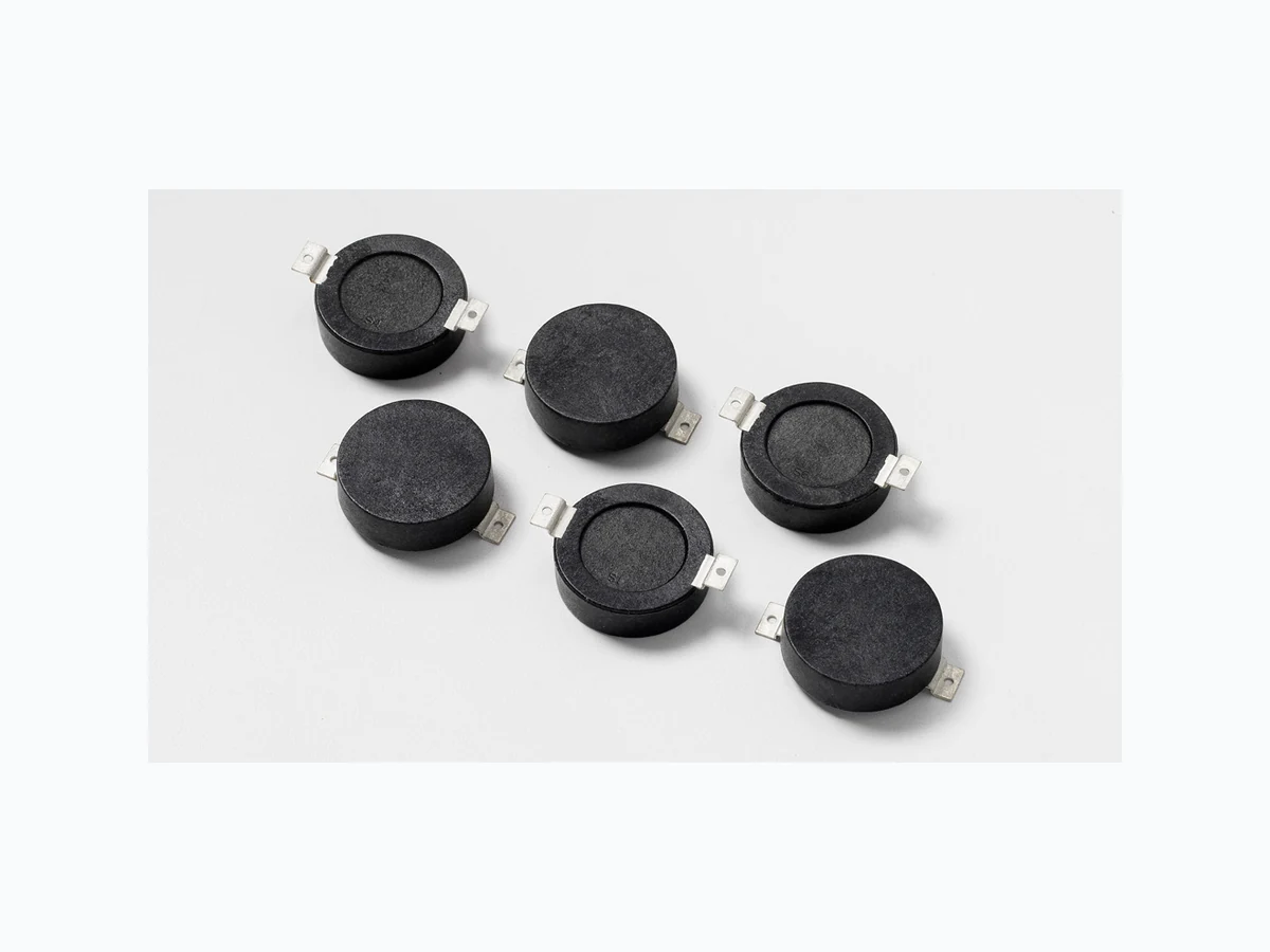
© 2017 Littelfuse, Inc. Specifications are subject to change without notice. Revised: 09/14/17 Metal-Oxide Varistors (MOVs) Surface Mount Varistors > SM20 Series Part Numbering System For “VARISTOR” Max Voltage Rating M(AC) (Two or three digits -- refer to ratings and specifications table) V 275 SM20 SM20 SERIES Soldering Pad Layout H2 t W D Product Dimensions Symbol Millimeters Min Max D (diameter) --- 26 H1 --- 10.5 H2 1. 0 -- t 0.50 0.70 S1 32.5 35 S2 3.0 4.5 W 6.2 6.6 Packaging 192 mm 30 mm typical 192 mm 30 mm typical 8.4 mm typical Radius 30 mm typical 11.7 mm pocket depth Standard Packaging is in "Waffle" trays: Quantity per tray: 36 pieces Quantity per box: 108 pieces Operating Ambient T emperature Range (TA) -40°C to +85°C Storage T emperature Range(T STG) -55°C to 125°C Solvent Resistance MIL STD 202, Method 215 Moisture Sensitivity Level 1, J-STD-020 Lead Material Folded Tin Plated Metal Leads Soldering Characteristics J-STD-002 Coating Molded Plastic Meets UL94 V-0 Requirement Physical Specifications Environmental Specifications Disclaimer Notice - Information furnished is believed to be accurate and reliable. However, users should independently evaluate the suitability of and test each product selected for their own applications. Littelfuse products are not designed for, and may not be used in, all applications. Read complete Disclaimer Notice at www.littelfuse.com/disclaimer-electronics.