
SM20_09 VISHAY
Document overview
- Manufacturer or author: Provided By www.digicamel.com(FREE DATASHEET DOWNLOAD SITE)
- PDF pages: 5
Technical content
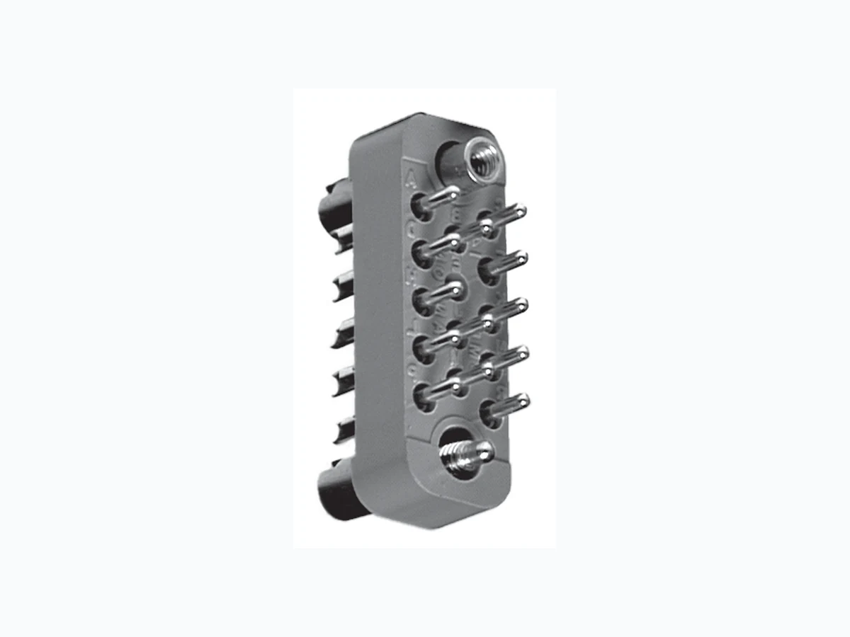
Document Number: 36010 For technical questions contact: connectors@vishay.com www.vishay.com Revision: 05-May-09 16 Rack and Panel Connectors Subminiature Rectangular SM20 Vishay Dale ELECTRICAL SPECIFICATIONS Current Rating: 7.5 A Breakdown Voltage: At sea level: 2000 V RMS At 70 000 feet [21 336 meters]: 500 VRMS PHYSICAL SPECIFICATIONS Number of Contacts: 5, 7, 11, 14, 20, 26, 34, 42, 50, 75 Contact Spacing: 0.120" [3.05 mm] Contact Gauge: #20 AWG Minimum Creepage Path Between Contacts: 0.080" [2.03 mm] Minimum Air Space Between Contacts: 0.050" [1.27 mm]
FEATURES
- Lightweight Polarized by guides or screwlocks Screwlocks lock connectors together to withstand vibration and accidental disconnect Overall height kept to a minimum Floating contacts aid in alignment and in withstanding vibration Contacts, precision machined and individually gauged, provide high reliability Insertion and withdrawal forces kept low without increasing contact resistance Contact plating provides protection against corrosion, assures low contact resistance and ease of soldering
APPLICATIONS
For use wherever space is at a premium and a high quality connector is required in avionics, automation, communications, controls, instrumentation, missiles, computers and guidance systems. MATERIAL SPECIFICATIONS Contact Pin: Brass, gold plated Contact Socket: Phosphor bronze, gold plated (Beryllium copper available on request) Guides: Stainless steel, passivated Screwlocks: Stainless steel, passivated Standard Body: Glass-filled diallyl phthalate per MIL-M-14, Model GDI-30F, green SMS20 SMP20 DIMENSIONS in inches [millimeters] SMS With Fixed Standard Guides 0.220 [5.59] 0.156 [3.96] Typ. See Detail B 0.470 [11.94] 0.190 [4.83] Typ. 2-56 UNC-2A Threads Typ. SMDS - DETAIL B Dip Solder Contact Option 0.187 [4.75] Typ. 0.030 [0.762] Typ. SMP With Fixed Standard Guides 0.040 [1.02] Dia. Typ. 0.220 [5.59] 0.120 [3.05] See Detail C 0.046 [1.17] Dia. Solder Cup #20 AWG Typ. 0.141 [3.58] Typ. 0.530 [13.46] SMDP - DETAIL C Dip Solder Contact Option 0.040 ± 0.001 [1.02 ± 0.025] Dia. Typ. 0.030 [0.762] Typ. 0.187 [4.75] Typ. 0.141 [3.58] Typ. SMS With Fixed (SL) Screwlocks 0.110 [2.79] 2-56 UNC-2A Thread is standard 0.520 [13.21] 0.220 [5.59] SMP With Turnable (SK) Screwlocks 0.920 [23.37] 0.220 [5.59] 0.120 [3.05] SMS With Turnable (SK) Screwlocks 0.910 [23.11] 0.220 [5.59] 0.046 [1.17] Wide x 0.062 [1.57] Deep Typ. 0.110 [2.79] 2-56 UNC-2A Thread is standard SMP With Fixed (SL) Screwlocks 0.120 [3.05] 0.220 [5.59] 0.530 [13.46]
www.vishay.com For technical questions contact: connectors@vishay.com Document Number: 36010 SM20 Vishay Dale Rack and Panel Connectors Subminiature Rectangular DIMENSIONS in inches [millimeters] TERMINAL VARIATIONS in inches [millimeters] SMP With Turnable (SK030) Screwlocks 0.120 [3.05] 0.046 [1.17] Wide x 0.062 [1.57] Deep Typ. 0.590 [14.99]0.220 [5.59] 0.156 [3.96] Dia. SMP With Turnable (SK035) Screwlocks View A-A Typ. A 0.120 [3.05] 0.610 [15.49] A 0.220 [5.59] 0.093 [2.36] Hex Typ. 0.156 [3.96] Dia. SMS With Turnable (SK035) Screwlocks 2-56 UNC-2A Thread is standard 0.110 [2.79] 0.220 [5.59] 0.595 [15.11] SMP With Turnable (SK030) Screwlocks 0.120 [3.05] 0.046 [1.17] Wide x 0.062 [1.57] Deep Typ. 0.590 [14.99]0.220 [5.59] 0.156 [3.96] Dia. DIP SOLDER PC BOARD MOUNTING PATTERNS Male (SMP) Connector is shown - Female is opposite. Contact row and Mating Hole C to C Dimensions also applies to Solder Cup Connectors.
14 CONTACTS11 CONTACTS7 CONTACTS5 CONTACTS
42 CONTACTS 50 CONTACTS 75 CONTACTS
34 CONTACTS26 CONTACTS20 CONTACTS
0.125 [3.18] Typ. LL 1.250 [31.75] Ref. 1.562 [39.67] 0.093 [2.36] Dia. Typ. 0.324 [8.23] Ref. 0.108 [2.74] Typ. 0.156 [3.96] Typ. 0.054 [1.37] Typ. 0.0625 [1.59] Typ. 0.110 [2.79] 0.220 [5.59] 1.500 [38.10] Ref. 0.093 [2.36] Dia. Typ. 1.812 [46.02] 0.540 [13.72] Ref. 0.108 [2.74] Typ. 0.0625 [1.59] Typ. 0.156 [3.96] Typ. 0.250 [6.35] Ref. 0.531 [13.49] 0.108 [2.74] Ref. 0.093 [2.36] Dia. Typ. 0.054 [1.37] Typ. 0.140 [3.56] Typ. 0.0625 [1.59] Typ. 0.093 [2.36] Dia. Typ. 0.054 [1.37] Typ. 0.108 [2.74] Ref. 0.375 [9.53] Ref. 0.625 [15.88] 0.0625 [1.59] Typ. 0.216 [5.49] Ref. 0.108 [2.74] Typ. 0.0625 [1.59] Typ. 0.750 [19.05] 0.500 [12.70] Ref. 0.093 [2.36] Dia. Typ. 0.125 [3.18] Typ. 0.750 [19.05] Ref. 1.0 [25.40] 0.093 [2.36] Dia. Typ. 0.108 [2.74] Typ. 0.216 [5.49] Ref. 0.0625 [1.59] Typ. 0.125 [3.18] Typ. 1.000 [25.40] Ref. 0.216 [5.49] Ref. 1.25 [31.75] 0.093 [2.36] Dia. Typ.0.0625 [1.59] Typ. 0.108 [2.74] Typ. 0.125 [3.18] Typ. 1.000 [25.40] Typ. 0.054 [1.37] Typ. 0.0625 [1.59] Typ. 1.312 [33.32] 0.324 [8.23] Ref. 0.093 [2.36] Dia. Typ. 0.108 [2.74] Typ. 0.156 [3.96] Typ. 0.0625 [1.59] Typ. 1.812 [46.02] 1.500 [38.10] Ref. 0.054 [1.37] Typ. 0.093 [2.36] Dia. Typ. 0.108 [2.74] Typ. 0.156 [3.96] Typ. 0.324 [8.23] Ref. 0.625 [15.88] 0.0625 [1.59] Typ. 0.108 [2.74] Typ. 0.216 [5.49] Ref. 0.093 [2.36] Dia. Typ. 0.375 [9.53] Ref. 0.125 [3.18] Typ. B A B A C B A C B A ABC C B A C BA ABC B A BC AC
Rack and Panel Connectors Subminiature Rectangular Vishay Dale Document Number: 36010 For technical questions contact: connectors@vishay.com www.vishay.com Revision: 05-May-09 18 DIMENSIONS in inches [millimeters] NOTE: The views below show the wiring side of a pin model connector (female is opposite). So cket hardware is assembled at “A” contact end of a pin model connector.
42 CONTACTS34 CONTACTS26 CONTACTS
14 CONTACTS 20 CONTACTS5 CONTACTS 7 CONTACTS 11 CONTACTS
75 CONTACTS50 CONTACTS
75 CONTACTS
34 THRU 50 CONTACTS
0.090 [2.29] Typ. 0.156 [3.96] Typ. 0.090 [2.29] Typ. 0.156 [3.96] Typ. Male Screwlock Pin or Guide Pin Female Guide Socket Female Screwlock Socket or Guide Socket 0.220 [5.59] 0.560 [14.22] 1.812 [46.02] 2.06 [52.32] Male Guide Pin 0.720 [18.29] 0.170 [4.32] 1.50 [38.10] 1.25 [31.75] 0.340 [8.64] 0.250 [6.35] 0.340 [8.64] 0.500 [12.70] 1.56 [39.62] 1.312 [33.32] 0.500 [12.70] 0.340 [8.64] 0.250 [6.35] 1.82 [46.23] 1.562 [39.68] A D H L P T W Z c B E J M R U X a C F K N S V Y b d A E K P U Y CC HH MM B F L R V Z DD JJ C H M S W AA EE KK NN D J N T X BB FF LL A E K P U Y CC HH MM SS WW B F L R V Z DD JJ NN TT C H M S W AA EE KK PP UU XX D J N T X BB FF LL RR VV A H P W c j r x AD AL AT AZ BF B J R X d k s y AE AM AU BA C K S Y f m t z AF AN AV BB BH D L T Z g n u AA A H AP AW BC E M U a h p v AB AJ AR AX BO BJ F N V b i p w AC AK AS AY BE A E K P U Y CC HH MM SS WW a e b XX ZZ TT NN JJ DD Z V R L F B C H M S W AA EE KK PP UU YY c f D J N T X BB FF LL RR VV d 0.500 [12.70] 0.340 [8.64]0.250 [6.35] 1.812 [46.02] 2.06 [52.32] A 0.230 [5.84] 0.090 [2.29] R Typ. 0.780 [19.81]0.531 [13.49] B E D C A A C E H B F D 0.625 [15.88] 0.870 [22.10] 0.230 [5.84] 0.340 [8.64] 0.170 [4.32] 0.625 [15.88] 0.870 [22.10] A D H L B E J C F K M 0.170 [4.32] 1.25 [31.75] 1.0 [25.40] 0.340 [8.64] A D H L P T W B E J M R U F K N S V X C 0.170 [4.32] 0.750 [19.05] 1.0 [25.40] 0.340 [8.64] A D H L B E R C F K N J M P
www.vishay.com For technical questions contact: connectors@vishay.com Document Number: 36010 SM20 Vishay Dale Rack and Panel Connectors Subminiature Rectangular Note (1) To order complete connector with hardware supplied unassembled, add suffix “UA” on end of hardware designation. PANEL CUTOUT in inches [millimeters] NUMBER OF CONTACTS A B C D FIGURE 5 0.230 [5.84] 0.531 [13.49] 0.410 [10.41] - I 7 0.230 [5.84] 0.625 [15.88] 0.500 [12.70] - 11 0.340 [8.64] 0.625 [15.88] 0.530 [13.46] - 14 0.340 [8.64] 0.750 [19.05] 0.620 [15.75] - 20 0.340 [8.64] 1.0 [25.40] 0.910 [23.11] - 26 0.340 [8.64] 1.25 [31.75] 1.16 [29.46] - 34 0.500 [12.70] 1.312 [33.32] 1.16 [29.46] 0.343 [8.71] II 42 0.500 [12.70] 1.562 [39.68] 1.41 [35.81] 0.343 [8.71] 50 0.500 [12.70] 1.812 [46.02] 1.66 [42.16] 0.343 [8.71] 75 0.720 [18.29] 1.812 [46.02] 1.66 [42.16] 0.562 [14.28] III FIGURE I 0.093 [2.36] Dia. Typ.D B C A A D 0.312 [7.93] B C A B 0.093 [2.36] C Dia. Typ. 0.218 [5.54] FIGURE III 0.093 [2.36] FIGURE II 0.093 [2.36]
ORDERING INFORMATION
EXAMPLES: SMBS20-26SK035 = Female, 26 beryllium copper socket contacts with socket head knobs on turnable screwlocks for #20 AWG wiring. SMP20-14SL3 = Male, 14 contact pins, fixed screwlocks with 3-48 threads for #20 AWG wiring. B CONTACT TYPE (OPTIONAL) B = Beryllium copper, socket contacts (Solder cup) D = Dip solder contacts C CONTACTS (OPTIONAL) Closed entry socket contacts only. Omit for standard contacts. 027 (1) HARDWARE OPTIONS (Omit if no hardware desired) 027 = Slotted cres guides 0.090" [2.29 mm] diameter SK = Turnable screwlocks with 2-56 threads SK3 = Turnable screwlocks with 3-48 threads SL = Fixed screwlocks with 2-56 threads SL3 = Fixed screwlocks with 3-48 threads SK030 = Turnable screwlocks with short slotted knobs SK035 = Turnable screwlocks with socket head knobs SK3030 = Turnable screwlocks with short slotted knobs with 3-48 threads SK3035 = Turnable screwlocks with socket head knobs with 3-48 threads CONTACT SIZE #20 AWG S CONTACT STYLE P = Pin S = Socket SM MODEL Subminiature R (OPTIONAL) (OPTIONAL) R = Reversed guides or screwlocks Omit for standard 5, 7, 11, 14, 20, 26, 34, 42, 50, 75 NUMBER OF CONTACTS G PLATING Optional plating available: G = Gold (0.00003 thick) over nickel G5 = Gold (0.00005 thick) over nickel Omit designator for gold (0.00001 thick) over nickel
Document Number: 91000 www.vishay.com Revision: 11-Mar-11 1 Disclaimer Legal Disclaimer Notice Vishay ALL PRODUCT, PRODUCT SPECIFICATIONS AND DATA AR E SUBJECT TO CHANGE WITHOUT NOTICE TO IMPROVE RELIABILITY, FUNCTION OR DESIGN OR OTHERWISE. Vishay Intertechnology, Inc., its affiliates, agents, and employees, and all persons acting on its or their behalf (collectivel y, “Vishay”), disclaim any and all liability for any errors, inaccuracies or incompleteness contained in any datasheet or in any other disclosure relating to any product. Vishay makes no warranty, representation or guarantee regarding the suitability of the products for any particular purpose or the continuing production of any product. To the maximum extent permitted by applicable law, Vishay disclaims (i) any and all liability arising out of the application or use of any product, (ii) any and all liability, incl uding without limitation specia l, consequential or incidental dama ges, and (iii) any and all impl ied warranties, including warran ties of fitness for particular purpose, non-infringement and merchantability. Statements regarding the suitability of pro ducts for certain types of applications are based on Vishay’s knowledge of typical requirements that are often placed on Vishay products in gene ric applications. Such statements are not binding statements about the suitability of products for a partic ular application. It is the customer’s responsibility to validate that a particu lar product with the properties described in th e product specification is su itable for use in a particul ar application. Parameters provided in datasheets an d/or specifications may vary in different applications and perfo rmance may vary over time. All operating parameters, including typical pa rameters, must be validated for each customer application by the customer’s technical experts. Product specifications do not expand or otherwise modify Vishay’s term s and conditions of purchase, including but not limited to the warranty expressed therein. Except as expressly indicated in writing, Vishay products are not designed for use in medical, life-saving, or life-sustaining applications or for any other application in which the failure of the Vishay product co uld result in person al injury or death. Customers using or selling Vishay products not expressly indicated for use in such applications do so at their own risk and agree to fully indemnify and hold Vishay and it s distributors harmless from and against an y and all claims, liabilities, expenses and damages arising or resulting in connection with such use or sale, including attorneys fees, even if such claim alleges that Vishay or its distributor was negligent regarding the design or manufacture of the part. Please contact authorized Vishay personnel to obtain written terms and conditions regarding products designed for such applications. No license, express or implied, by estoppel or otherwise, to any intellectual property rights is granted by this document or by any conduct of Vishay. Product names and markings noted herein may be trademarks of their respective owners.