
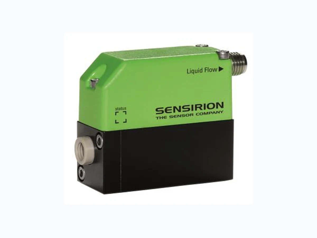
SLI ETC2
Document overview
- Manufacturer or author: Provided By www.digicamel.com(FREE DATASHEET DOWNLOAD SITE)
- PDF pages: 7
Technical content
www.sensirion.com Version 10 –February 2015 1/7 SLI Liquid Flow Meter Series Media Isolated Microfluidic Flow Meter Liquid flow rates up to 5 ml/min Non-invasive Measurement Different Interface Options 40 ms Flow Detection Response Time Product Summary Interface Options The SLI Liquid Flow Meter ena bles fast, non-invasive measurements of very low liquid flow in the µl/min- to ml/min-range. Excellent chemical resistance and bio - compatibility are ensured: The flow path of the SLI Liquid Flow Meter is formed by a simple, straight glass capillary. The f ourth generation MEMS sensors combine a thermal high precision sensor element with amplification circuits and digital intelligence for linearization and temperature compensation on one single microchip – the product’s core element. Digital - I2C-Bus - RS485-Bus - USB Cable Analog - Voltage Output (0-10 V) - Additional operation modes For more information on communication, please refer to page 2 of this document.
1 Sensing Performance
Table 1: Model specific performance of SLI (all data for medium H2O, 23°C) Parameter SLI-0430 SLI-1000 SLI-2000 Unit H2O Full scale flow rate 80 1000 5000 µl/min H2O Sensor output limita 120 1100 5500 µl/min Accuracy below full scale (whichever error is larger) 0.15 0.2 0.2 % of full scale Repeatability below full scale (whichever error is larger) 0.01 0.02 0.02 % of full scale Temperature coefficient (additional error / °C; whichever is larger) 0.003 0.004 0.004 % full scale / °C Mounting orientation sensitivityc <0.4 1.0 1.5 % of full scale Flow detection response time 63 40 ms Response time on power-up 120 ms Operating temperature +10…+50 °C Ambient storage temperatured -10…+60 °C Operating pressure 50 15 15 bar Proof pressure 150 30 30 bar aFlow rate at which the sensor output saturates. See Section 2 for performance between full scale and saturation point bMeasured value cMaximum additional offset when mounted vertically dNon-condensing, flow path empty
www.sensirion.com Version 10 –February 2015 2/7 Table 2: Model specific performance of SLI (all data for medium IPA, 23°C) Parameter SLI-0430 SLI-1000 SLI-2000 Unit IPA full scale flow rate 500 10’000 µl/min 80 ml/min Sensor output limita 600 11’000 µl/min 90 ml/min Accuracy below full scale (whichever error is larger) 20 20 10 % of m.v.b 1 1 0.5 % of full scale Repeatability below full scale (whichever error is larger) 1 1 1.5 % of m.v. 0.05 0.05 0.03 % of full scale Temperature coefficient (additional error / °C; whichever is larger) 0.5 0.025 0.02 % full scale / °C aFlow rate at which the sensor output saturates bMeasured value
1.1 Calibration Field Information
The SLI Liquid Flow meter s hold two calibrations, one for water (H2O) and one for isopropyl alcohol (IPA) . Each calibration is stored on a separate calibration field (CF): Calibration field 0: H2O (factory default) Calibration field 1: IPA The default calibration field (i.e. the active calibration field at power up) can be permanently changed via I 2C or RS485 commands. Alternatively, the default ca libration field can be changed using the USB -RS485 Sensor Viewer which is part of the Flow Meter Kit and also available in the download center on the Sensirion liquid flow webpage. www.sensirion.com/liquidflow-download
2 Specifications Charts
Figure 1: Flow meter accuracy and repeatability across the flow range. Relative error in % of measured value (left column) and absolute error in µl/min (right column) for H2O
www.sensirion.com Version 10 –February 2015 4/7
3 Communication with the Sensor
The SLI flow meter shows bidirectional, linear transfer characteristics. The product comes fully calibrated for water and IPA. Digital Sampling Time, 16 bit 74 ms Digital Sampling Time, 9 bit 1 ms
3.1 Electrical Specifications
Table 3: DC Characteristics Parameter Conditions Min. Typ. Max. Units Power Supply DC, VDD Sensor only 4 5 6 V RS485 cable 4 5 6 V Analog cable 12 24 36 V Operating Current VDD = 4-6 V, no load 5 5.5 6 mA RS485 cable 20 70 mA Analog cable 4.3 mA
3.2 Electrical Connector and Pinout
The flow meter is equipped with a male connector type M8, 4 -pin, threaded lock according to IEC 61076-2-101 (Ed. 1)/ IEC 60947 -5-2, and is compatible with Sensirion’s SCC1 interface cables. Table 3: Electrical pinout Pin
1 SDA (data)
2 GND
3 VDD
4 SCL (clock)
3.3 Communication via USB cable
The Sensirion USB Sensor Cable provides an easy to use USB Interface for laboratory and desktop use. For further information please see the SCC1-USB Sensor Cable datasheet, available on www.sensirion.com/liquidflow-download.
3.4 Digital Communication via RS485-Bus
The SCC1-RS485 Sensor Cable for flow sensors allows the communication via RS485 interface for use in a demanding industrial automation environment. In addition to the standard commands available in the I²C interface of the sensor, the incorporated microcontroller of the cable provides more complex logic such as a dispense volume totalizer, automatic dispense detection, automatic heater control and data buffer for asynchronous read-out. For further information please see the SCC1-RS485 Sensor Cable datasheet, available on www.sensirion.com/liquidflow-download.
3.5 Analog Communication
The SCC1-ANALOG Sensor Cable allows simple and quick readout of Sensirion’s liquid flow meters by converting the digital sensor reading to a 0...10.5 V analog voltage output. Additionally, a digital (high/low) output with two different modes of operation is available (Flow Switch / Volume Counter) For further information please see the SCC1-USB Sensor Cable datasheet, available on www.sensirion.com/liquidflow-download.
3.6 Digital Communication via I²C-Bus
Digital communication between a master and the SLI sensor runs via the standard I²C -interface. The physical interface consists of two bus lines, a data line (SDA) and a clock line (SCL) which need to be connected via pull -up resistors to the bus voltage of the system. These lines can be used on 3.3V or 5.0V level with a clock frequency of 100 kHz. For the detailed specifications of this I²C communication, please refer to specific I²C Application Notes from Sensirion.
www.sensirion.com Version 10 –February 2015 5/7
4 Fluidic Connection
Table 5: Fluidic Specifications and Pressure Rating Parameter SLI-0430 SLI-1000 SLI-2000 Wetted Materials: Internal sensor tube material Quartz Glass (Fused Silica) Borosilicate Glass 3.3 Fitting material PEEK Sealing material None FEP Fluid connector ports (Fittings) ¼-28 flat-bottom for 1/16” or 1/8” OD plastic tubinga Pressure drop (at full scale flow rate, H2O, 23°C) 1 mbar <1 mbar <1 mbar Pressure drop (at full scale flow rate, IPA, 23°C) 7 mbar 5 mbar 2 mbar Total internal volume 5 µl 25 µl 80 µl a1/8” OD tubing with 2 mm minimum ID is recommended for the SLI-2000. For more information on the flui dic connection please find: “Application Note Sensor Ports and Tubing Connections” in the Download Center on our webpage (www.sensirion.com/liquidflow-download).
5 Mechanical Specifications
Table 6: Mechanical Specifications Parameter SLI-0430 SLI-1000 SLI-2000 Largest dimensions 58 x 42.5 x 20 mm Total mass 53 g Inner diameter d 430 µm 1.0 mm 1.8 mm Protection class IP 65 All dimensions in mm SLI-0430 SLI-1000 / SLI-2000
www.sensirion.com Version 10 –February 2015 6/7
6 Ordering Information
For OEM applicatio ns, the flow meter can be purchased in larger quantities without any additional parts. For optimum performance, Sensirion recommends using the SLI flow meter s in combination with the SCC1 interface cables. For laboratory use and technology evaluation, the Flow Meter Kit SLI-XXXX can be ordered. This laboratory-package contains: Liquid Flow Meter SLI-XXXX Fitting Material for 1/8’’ tubing PC Software (Viewer & Data Export Tool) SCC1-USB Sensor Cable with USB connector for plug-and-play connection to a PC SCC1-Analog Sensor Cable with 0 -10 V voltage output. Table 9: Ordering information Product Article Number SLI-0430 Liquid Flow Meter 1-100836-02 SLI-1000 Liquid Flow Meter 1-100835-01 SLI-2000 Liquid Flow Meter 1-100895-01 Flow Meter Kit SLI-0430 1-100893-01 Flow Meter Kit SLI-1000 1-100879-01 Flow Meter Kit SLI-2000 1-100894-01 Interface Cables: SCC1-RS485 Sensor Cable Pigtail 2m 1-100804-01 SCC1-RS485 Sensor Cable Pigtail 5m 1-101122-01 SCC1-ANALOG Sensor Cable Pigtail 2m 1-101072-01 SCC1-ANALOG Sensor Cable Pigtail 10m 1-101219-01 SCC1-USB Sensor Cable 2m 1-101007-01
www.sensirion.com Version 10 –February 2015 7/7 Important Notices Warning, personal injury Do not use this product as safety or emergency stop devices or in any other application where failure of the product could result in personal injury (including death). Do not use this product for applications other than its intended and authorized use. Before installing, handling, using or servicing this product, please consult the datasheet and application notes. Failure to comply wit h these instructions could result in death or serious injury. If the Buyer shall purchase or use SENSIRION products for any unintended or unauthorized application, Buyer shall defend, indemnify and hold harmless SENSIRION and its officers, employees, subsi diaries, affiliates and distributors against all claims, costs, damages and expenses, and reasonable attorney fees arising out of, directly or indirectly, any claim of personal injury or death associated with such unintended or unauthorized use, even if SE NSIRION shall be allegedly negligent with respect to the design or the manufacture of the product. ESD Precautions The inherent design of this component causes it to be sensitive to electrostatic discharge (ESD). To prevent ESD -induced damage and/or degradation, take customary and statutory ESD precautions when handling this product. Warranty SENSIRION warrants solely to the original purchaser of this product for a period of 12 months (one year) from the date of delivery that this product shall be of the qu ality, material and workmanship defined in SENSIRION’s published specifications of the product. Within such period, if proven to be defective, SENSIRION shall repair and/or replace this product, in SENSIRION’s discretion, free of charge to the Buyer, provided that: notice in writing describing the defects shall be given to SENSIRION within fourteen (14) days after their appearance; such defects shall be found, to SENSIRION’s reasonable satisfaction, to have arisen from SENSIRION’s faulty design, material, or workmanship; the defective product shall be returned to SENSIRION’s factory at the Buyer’s expense; and the warranty period for any repaired or replaced product shall be limited to the unexpired portion of the original period. This warranty does not apply to any equipment which has not been installed and used within the specifications recommended by SENSIRION for the intended and proper use of the equipment. EXCEPT FOR THE WARRANTIES EXPRESSLY SET FORTH HEREIN, SENSIRION MAKES NO WARRANTIES, EITHER EXPRESS OR IMPLIED, WITH RESPECT TO THE PRODUCT. ANY AND ALL WARRANTIES, INCLUDING WITHOUT LIMITATION, WARRANTIES OF MERCHANTABILITY OR FITNESS FOR A PARTICULAR PURPOSE, ARE EXPRESSLY EXCLUDED AND DECLINED. SENSIRION is only liable for defects of this product arising under the conditions of operation provided for in the datasheet and proper use of the goods. SENSIRION explicitly disclaims all warranties, express or implied, for any period during which the goods are operated or stored not in accordance with the technical specifications. SENSIRION does not assume any liability arising out of any application or use of any product or circuit and specifically disclaims any and all liability, including without limitation consequential or incidental damages. All operating parameters, including without limitation recommended parameters, must be validated for each customer’s applications by customer’s technical experts. Recommended parameters can and do vary in different applications. SENSIRION reserves the right, without further notice, (i) to change the product specifications and/or the information in this document and (ii) to improve reliability, functions and design of this product. Copyright © 2001-2015, SENSIRION. CMOSens® is a trademark of Sensirion All rights reserved CE, RoHS, REACH and WEEE Statement The flow meters of the SLI series comply with requirements of the following directives and regulations: The device fully complies with norm EN 50081 -2 (Emission Test Series), EN 50082-2 (Immunity Test Series) and ES D protection when used in combination with the SCC1 -RS485 or SCC1-ANALOG Sensor Cables. EU Directive 1907/2006/EC concerning Registration, Evaluation, Authorization and Restriction of Chemicals (REACH) EU Directive 2002/96/EC on waste electrical and electr onic equipment (WEEE), OJ13.02.2003; esp. its Article 6 (1) with Annex II. EU Directive 2002/65/EC on the restriction of certain hazardous substances in electric and electronic equipment (RoHS), OJ01.01.2011 Headquarters and Subsidiaries SENSIRION AG Laubisruetistr. 50 CH-8712 Staefa ZH Switzerland phone: +41 44 306 40 00 fax: +41 44 306 40 30 info@sensirion.com www.sensirion.com Sensirion Inc., USA phone: +1 805 409 4900 info_us@sensirion.com www.sensirion.com Sensirion Japan Co. Ltd. phone: +81 3 3444 4940 info@sensirion.co.jp www.sensirion.co.jp Sensirion Korea Co. Ltd. phone: +82 31 345 0031 3 info@sensirion.co.kr www.sensirion.co.kr Sensirion China Co. Ltd. phone: +86 755 8252 1501 info@sensirion.com.cn www.sensirion.com.cn Sensirion AG (Germany) phone: +41 44 927 11 66 info@sensirion.com www.sensirion.com To find your local representative, please visit www.sensirion.com/contact