
DATASHEET SEARCH SITE
Document overview
- Manufacturer or author: Provided By www.digicamel.com(FREE DATASHEET DOWNLOAD SITE)
- PDF pages: 5
Technical content
Features
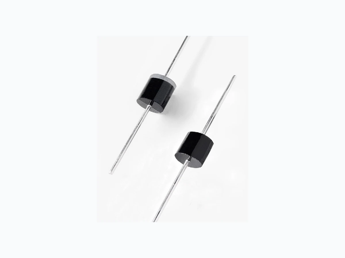
The AEC-Q101 qualified SLD Series is packaged in a highly reliable industry standard P600 axial leaded package and is designed to provide precision overvoltage protection for sensitive electronics.
Description
Maximum Ratings and Thermal Characteristics (TA=25OC unless otherwise noted) Agency Approvals
- Hi reliability application and automotive grade AEC-Q101 qualified with TJ 175°C
- VBR @ TJ= VBR@25°C x (1+αT x (TJ - 25)) (αT :Temperature Coefficient, typical value is 0.1%)
- Glass passivated chip junction in P600 package
- Meet ISO7637 and ISO16750 load dump test; 2200W peak pulse capability at 10μs × 150ms waveform, repetition rate (duty cycles): 0.01%
- Fast response time: typically less than 1 .0ps from 0 Volts to BV min
- Excellent clamping capability
- Typical failure mode is short from over-specified voltage or current
- Whisker test is conducted based on JEDEC JESD201A per its table 4a and 4c
- IEC-61000-4-2 ESD 30kV(Air), 30kV (Contact)
- ESD protection of data lines in accordance with IEC 61000-4-2
- EFT protection of data lines in accordance with IEC 61000-4-4
- Low incremental surge resistance
- High temperature soldering guaranteed: 260°C+5/-0°C / 10s ±1sec / 0.375” ,(9.5mm) lead length, 5 lbs., (2.3kg) tension
- Plastic package is flammability rated V-0 per Underwriters Laboratories
- Matte tin lead–free plated
- Halogen free and RoHS compliant
- Pb-free E3 means 2nd level interconnect is Pb- free and the terminal finish material is tin(Sn) (IPC/ JEDEC J-STD-609A.01) Parameter Symbol Value Unit Peak Pulse Power Dissipation 10ms x 150ms Test Waveform PPPM 2200 W Peak Pulse Power Dissipation 10μs x 1000μs Test Waveform PPPM 5000 W Steady STLte Power Dissipation on Infinite Heat Sink at TL=75ºC (Fig. 6) PD 8.0 W Peak Forward Surge Current, 8.3ms Single Half Sine Wave (Note 3) IFSM 600 A Maximum InsTLnTLneous Forward VolTLge at 100A for Unidirectional Only VF 3.5 V Operating Junction and Storage Temperature Range TJ, TSTG -55 to 175 °C Typical Thermal ResisTLnce Junction to Lead RuJL 8.0 °C/W Typical Thermal ResisTLnce Junction to Ambient RuJA 40 °C/W SLD Series Functional Diagram Bi-directional Uni-directional Cathode Anode Bi-directional Uni-directional RoHS Pb e3
© 2016 Littelfuse, Inc. Specifications are subject to change without notice. Revised: 09/10/16 Axial Leaded – 2200W > SLD series Electrical Characteristics (TA=25°C unless otherwise noted) Notes: 1 . VBR measured after IT applied for 300µs, IT= square wave pulse or equivalent. 2. Surge current waveform per 10μs x 1000μs exponential wave and derated per Fig. 4. 3. All terms and symbols are consistent with ANSI/IEEE C62.35 Part Number (Uni) Part Number (Bi) Breakdown Voltage VBR @ IT (V) Test Current IT (mA) Reverse Stand off Voltage VR (Volts) Maximum Reverse Leakage @ VR IR (µA) Maximum Peak Pulse Current Ipp (A) Maximum Clamping Voltage @ IPP VC (V) Agency Approval MIN MAX I-V Curve Characteristics PPPM Peak Pulse Power Dissipation -- Max power dissipation VR Stand-off Voltage -- Maximum voltage that can be applied to the TVS without operation VBR Breakdown Voltage -- Maximum voltage that flows though the TVS at a specified test current (IT) VC Clamping Voltage -- Peak voltage measured across the TVS at a specified Ippm (peak impulse current) IR Reverse Leakage Current -- Current measured at VR VF Forward Voltage Drop for Uni-directional Vc VBR VR IR IT Ipp V Uni-directional VF Vc VBR VR IR IT Ipp V VcVBRVR Ipp IR IT Bi-directional
© 2016 Littelfuse, Inc. Specifications are subject to change without notice. Revised: 09/10/16 Axial Leaded – 2200W > SLD series Physical Specifications Weight 0.07oz., 2.1g Case P600 molded plastic body over passivated junction. Polarity Color band denotes the cathode except Bipolar. T erminal Matte Tin axial leads, solderable per JESD22-B102. Soldering Parameters Flow/Wave Soldering (Solder Dipping) Environmental Specifications High T emp. Storage JESD22-A103 HTRB JESD22-A108 T emperature Cycling JESD22-A104 H3TRB JESD22-A101 RSH JESD22-B106 0.5 1.0 1.5 2.0 2.5 3.0 65 70 75 80 85 Ri(ohm) Vs(volt) ISO7637 5A 12V Test System 3.5 4.0 Td:400ms SLD15U-017 & SLD15-018 load dump Figure 7 - SOA Chart 123 1331 43 153 163 173 Ri(ohm) Vs(volt) ISO7637 5A 24V Test System SLD28U-017 load dump Td:350ms Peak T emperature : 260°C+5/-0°C Dipping Time : 10s ±1 seconds Soldering : 1 time
© 2016 Littelfuse, Inc. Specifications are subject to change without notice. Revised: 09/10/16 Axial Leaded – 2200W > SLD series Part Numbering System Packing Options Part Number Component Package Quantity Packaging Option Packaging Specification SLDxxXXX P600 800 Tape & Reel EIA STD RS-296 SLDxxXX-B P600 100 BOX Littelfuse Spec. VBR VOLTAGE CODE (Refer to the Electrical Characteristics table) TYPE CODE: U-017 Uni-Directional -018 Bi-Directional OPTION CODE: BLANK Reel Tape -B Bulk Packaging SERIES CODE SLD XX U-017 X Part Marking System F SLDXXX YYWW Trace Code Marking YY:Year Code WW: Week Code Product Type Littelfuse Logo Cathode Band (for Uni-directional products only) T ape and Reel Specification 0.394+/-0.020 2.75 0.047 (330.2) Recess Depth Max. 0.75 (19.05) Off Center either side 0.028(0.7) Dimensions are in inches/mm 0.236 (65.0) (10.0+/-0.5) (53.0+2.0/-1.0) (6.0)(1.2) (69.85) 13.0 (76.2) 3.0 0.68 (17.27) Direction of Feed Dimensions Dimensions Inches Millimeters Min Max Min Max A 1 .000 - 25.40 - B 0.340 0.360 8.60 9.10 C 0.048 0.052 1 .22 1 .32 D 0.340 0.360 8.60 9.10P600 D A A C B Cathode Band (for Uni-directional products only)