

 Download PDF
SLC ITT
Document overview
- PDF pages: 16
Technical content
Page 1
Engineering Quick Reference Selection Guide
| 2 Position | 4 Position | 5 Position | |||
| Contact Arrangement | Plug Receptacle 1 2 2 1 | Contact Cannon | Plug Receptacle 2 2 1 3 3 1 5 4 4 5 | ||
| Features | Inline | Feed Thru | Inline | PCB | Inline |
| Clip Lock | Clip Lock | Clip Lock | Snap Lock | Snap Lock | |
| Specifications | CS-216 | CS-216 | CS-216 | CS-206 | CS-206 |
| Plug | 086-0066-000 w/Wedgelock 086-0058-000 Standard | 086-0058-000 Standard | Contact Cannon | 098532-0000 (5 A) 098532-001 (13 A) | 098532-0000 (5 A) 098532-001 (13 A) |
| Receptacle | 086-0061-000 w/Wedgelock | 083-0242-000 | Contact Cannon | 098531-0000 (5 A) 098531-0001 (13 A) | 098530-0000 (5 A) 098530-0001 (13 A) |
| Terminals | See page 14 | See page 14 | Contact Cannon | See page 14 | See page 14 |
How to Order
SLC 5 T 13 0 0
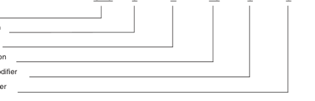
Series Prefix
Size/Configuration
Connector Type
Contact Termination
Material/Finish Modifier
Mechanical Modifier
Series Prefix
Contact Termination
SLC - Snap-Lock Circular
5 - 5 A 13 - 13 A
Size/Configuration
Material/Finish Modifier
5-5 Cavity Housing
0 -Standard Assembly (Silicone Elastomer)
8-8 Cavity Housing 10-10 Cavity Housing
1 -Fluorosilicone Elastomer
15-15 Cavity Housing
Mechanical Modifier
Connector Type
0 -Standard Assembly
P - Plug, In-line (Cable-to-Cable)\* R - Receptacle, In-line (Cable-to-Cable) T - Receptacle, Snap-thru B - Receptacle, PCB
\*Note: In-line Plug mates with all 3 receptacle types (In-line, Snap-thru, and PCB.)
Page 2
Engineering Quick Reference Selection Guide
Plug
Receptacle
| 8 Position 10 Position 15 Position | ||||||||
| Receptacle Plug 1 2 2 1 7 8 3 3 7 6 4 8 5 4 5 6 | Receptacle Plug 3 4 4 3 2 2 1 10 5 5 10 1 9 9 6 6 8 7 7 8 | 3 4 4 12 3 2 11 12 13 5 13 15 11 14 5 2 1 10 9 15 8 14 6 8 10 1 6 9 7 7 | ||||||
| PCB | Inline | Snap-thru | PCB | Inline | Snap-thru | Snap-thru | ||
| Snap Lock (Double) | Snap Lock (Double) | Snap Lock (Double) | Snap Lock (Double) | Snap Lock (Double) | Snap Lock (Double) | Snap Lock (Double) | ||
| CS-210 | CS-210 | CS-210 | CS-206 | CS-206 | CS-210 | CS-210 | ||
| 098532-0010 | 098532-0008 | 098532-0010 | 098532-0002 (5 A) 098532-0003 (13 A) | 098532-0002 (5 A) 098532-0003 (13 A) | 098532-0002 (5 A) 098532-0003 (13 A) | 086-0060-000 | ||
| - | - | 098533-0010 | 098531-0002 (5 A) 098531-0003 (13 A) | 098530-0002 (5 A) 098530-0003 (13 A) | 098533-0002 098533-0003 | 086-0059-000 | ||
| See page 14 | See page 14 | See page 14 | See page 14 | See page 14 | See page 14 | See page 14 | ||
Page 3
The Snap Lock Environmental Series is environmentally sealed connector created for printed
circuit board, black box, cable-to-cable or bulkhead applications.
When your under-the-hood requirements call for tough performance, the SLC "snaps" into a tightly sealed connection that can withstand heat, shock and vibration. The connector is designed to preserve the integrity of the solid state package, while protecting against contaminants - even when unmated.
Gold, tin/lead plated stamped contacts add durability.
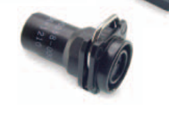
A rugged, thermoplastic receptacle body maximizes performance by withstanding temperature variances from -40°C to +150°C (material rating).
The SLC series is available in 2, 5, 8, 10, 15 contact cavity configurations. It can also be adapted to robotics assembly. Should you requirement demand higher density configurations, consult Customer Service.
Product Features and Benefits
- Current rating 5 A and 13 A versions
- Superior environmental sealing
- Material rating: -40°C to +150°C continuous
- Low millivolt drop
- Low contact resistance
operation at rated current
- Small footprint on P.C. board and low profile
- Available in sizes 2, 5, 8, 10, 15 contacts
- Adaptable to robotics assembly
- Crimp stamped gold, tin/lead plated contacts
- Hand insertable/removable contacts
Performance Specifications
Contact Resistance 10mΩ maximum Insulation Resistance 20MΩ minimum (USCAR) Current Rating 5 A signal continuous at 150°C all contacts, 2 position
- Latch with tactile and audible feedback
- Increases durability and provides for minimum installation
- Low installed cost
- Requires less PCB space
13 A power continuous at 150°C all contacts, 5 position and 10 position only
Dielectric Withstanding Voltage 1000 Vrms AC at sea level Applicable Cannon Specification SLC (CS-206) SLCT 5 & 10 (210) SLCT8 (216) SLCT 15 (206) Material Rating Operating Temperature -40°C to +150°C
Crimp Contacts Semi-automatic or hand crimpable or fully automatic Wire Size 20 - 16 AWG
Wire Insulation Sealing Range 1,98 (.078) to 3,30 (.130) dia. Contact Insertion No tool required. Suitable for automation. Contact Extraction Rear Removable Contact Retention 20 lbs. Minimum per contact Wire Strip Length 5,59 (.220) to 5,33 (.210)
Materials and Finishes
Connector Housing High temperature thermoplastic Contacts Copper alloy Finish Engaging area: Gold over nickel Crimp/P.C. tail area: Tin/lead over nickel - standard offering Tin/Lead over nickel - Option #2 all over
Environmental Seal High temperature silicone elastomer
Page 4
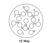
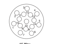
Contact Cavity Arrangements - Mating Face View
Plug
2
1 2
1
7
3
8 3 6
1 2
5 4
4 5
2 Way
5 Way
8 Way
3 4 2 5 1 10 9 6 8 7
10 Way
Receptacle
2
2 1
3 1
3 7 8
2 1
4
4 5
6 5
2 Way
5 Way
8 Way
3 4 2 1 5 10 9 6 8 7
10 Way
15 Way
Page 5
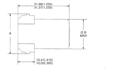
Plug, In-line\* (Cable-to-Cable) (Type P) SLC-5, SLC-10
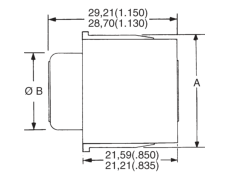
Front-Face View 5 Cavity Housing
In-line Plug\* (Mates with SLC types R, T, and B) Housing Size Rating
Part Number
5
5 A
098532-0011
5
13 A
098532-0001
10
5 A
098532-0002
10
13 A
098532-0003
Side View
Front-Face View
Plug Assembly
10 Cavity Housing
Description
A
ØB
SLC-5P5-00
27,81 (1.095)
18,03 (.710)
SLC-5P13-00
26,80 (1.055)
18,03 (.710)
SLC-10P5-00
34,92 (1.375)
24,15 (.990)
SLC-10P13-00
34,04 (1.340)
25,15 (.990)
\*Contact lead assemblies are customer terminated and installed. See page 14, part numbers 110238-0488, 110238-2003.
Page 6
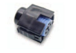
Receptacle, In-line\* (Cable-to-Cable) (Type R) SLC-5, SLC-10
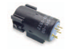
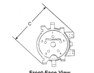
Front-Face View 5 Cavity Housing
In-line Receptacle\* (Mates with SLC type P) Housing Size Rating
Part Number
5
5 A
098530-0000
5
13 A
098530-0001
10
5 A
098530-0002
10
13 A
098530-0003
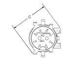
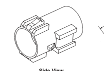
Side View
Front-Face View
Receptacle Assembly
10 Cavity Housing
Description
A
ØB C Ref.
SLC-5R5-00
24,13 (.950)
18,03 (.710) 24,38 (.960)
SLC-5R13-00
23,75 (.935)
18,03 (.710) 24,38 (.960)
SLC-10R5-00
31,24 (1.230)
25,15 (.990) 31,62 (1.245)
SLC-10R13-00
30,86 (1.215)
25,15 (.990) 31.62 (1.245)
\*Contact lead assemblies are customer terminated and installed. See page 16, part numbers 110238-0446, 110238-2004.
Square Flange
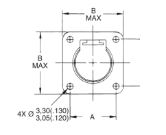
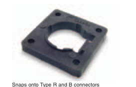
Materials and Finishes Material: Thermoplastic
Housing Size Part Number
A
Color: Black
5
066-9504.000 23,37 (.920)
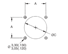
B Max.
ØC
31,24 (1.230)
32,51 - 31,75 (1.280 - 1.250)
066-9504-001 28,45 (1.120)
36,32 (1.430)
25,40 - 24,64 (1.000 - .970)
10
Page 7
Receptacle, Snap-thru\* (Type T) SLC-5, SLC-10
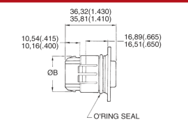
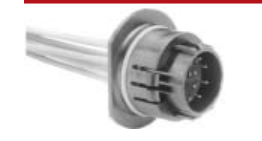
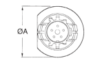
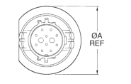
Side View
Front-Face View
Front-Face View
10 Position
5 Position
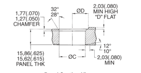
Panel Section View
Snap-thru Receptacle\* (Mates with SLC Type P) Housing Size Rating
Part Number Description
5
5 A 098533-0000 SLC-5T5-00
5
13 A 098533-0001 SLC-5T13-00
10
5 A 098533-0002 SLC-10T5-00
10
13 A 098533-0003 SLC-10T13-00
Panel Rear Face View
ØA
ØB
ØC
ØD
37,21 (1.465) 24,13 (.950)
25,60 (1.008) 15,62 (.615)
36,96 (1.455) 23,75 (.935)
25,48 (1.003) 15,34 (.605)
47,62 (1.875) 31,24 (1.230) 35,05 (1.380) 20,19 (.795) 47,37 (1.865) 30,86 (1.215) 34,92 (1.375) 19,94 (.785)
\*Contact lead assemblies are customer terminated and installed. See page 14, part numbers 110238-0446, 110238-2004.
Page 8
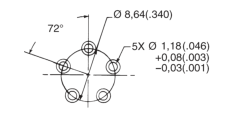
Receptacle, PCB\* (Type B) SLC-5, SLC-10
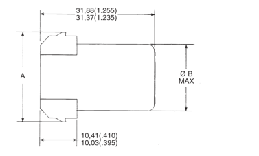
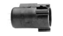
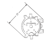
Front-Face View 5 Cavity Housing
In-line Receptacle\* (Mates with SLC Type P) Size Rating Part Number
Description
5 5 A 098531-0000 SLC-5B5-00
5 13 A 098531-0001 SLC-5B13-00 10 5 A 098531-0002 SLC-10B5-00
10 13 A 098531-0003 SLC-10B13-00 \*PCB Contacts are factory installed.
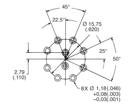
Recommended PCB Layout
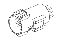
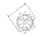
Front-Face View
Side View
10 Cavity Housing
In-Line Receptacle With PCB Contacts
A ØB
C Ref.
24,13 (.950)
18,03 (.710)
24,38 (.960)
23,75 (.935)
18,03 (.710)
24,38 (.960)
31,24 (1.230) 25,15 (.990)
31,62 (1.245)
30,86 (1.215) 25,15 (.990)
31,62 (1.245)
Page 9
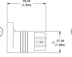
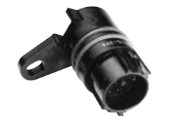
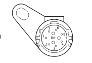
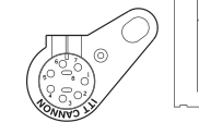
Receptacle, Snap-thru SLCT-8
Part No.: 098533-0010 (mates with 098532-0008)
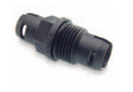
Receptacle, Feed-thru CLC-2
Part No.: 086-0057-000
13,85
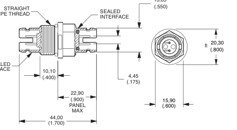
SEALED INTERFACE
Note: In-line plug and receptacle available.
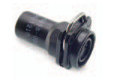
Plug, Feed-thru CLC-2
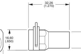
Part No.: 086-0058-000 With Silicone Grommet Seal Part No.: 086-0058-001 With Silicone Grommet Seal Part No.: 086-0058-002 With Fluorosilicone Seal
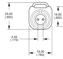
13,20 (.520)
A B
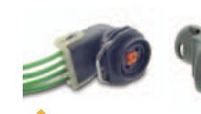
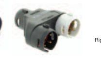
Right Angle CLC and CLC Y-Splice, please contact Product Management.
Page 10
Plug, Snap-thru SLC-15
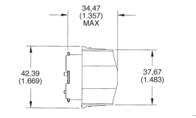
Part Number: 086-0060-000
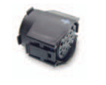
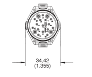
Receptacle, Snap-thru SLC-15
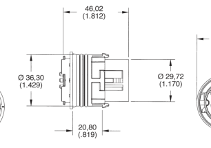
Part Number: 086-0059-000
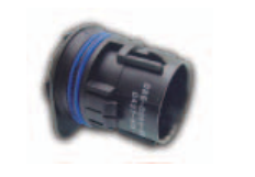
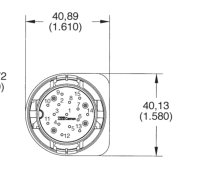
Consult factory for alternate layouts.
Page 11
Contacts, Stamped, 5 and 13 Amp
Socket (use in plugs)
Hooded Socket
Pin (use in receptacles)
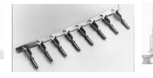
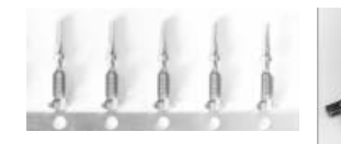
Reeled
Hooded Socket
Description
Socket Part Number
Pin Part Number
5 A
110238-1016 (030-2480-007)
110238-0446 (030-2464-007)
13 A
110238-2004 (030-2464-003)
Accessories
Sealing Plugs
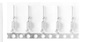
Socket Part Number
Number of Contacts
110238-0488 (030-2480-000)
4,500
110238-2003 (030-2480-003)
4,000
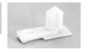
Connector Clip
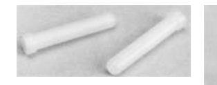
Material: Thermoplastic, Color: Natural
Material: Thermoplastic, Color: Natural
Part Number: 225-0093-000
Part Number: 225-0093-000 +125°C Rating
+125°C Rating
Mounting Hardware for use on In-line Receptacle (Cable-to-Cable) (Type R) Fits Ø6,35 (.250) hole x 0,51 (.020) thick panel.
Page 12
Extraction Tool
Contact Extraction Tool Part Number: 274-7068-001 Tip Part Number: 323-9519-000
A Standard CET - SLE/SLC is available for extraction of the individual crimp contacts. Insertion tool is not required.
Insertion / Extraction Instructions for Crimp Contacts
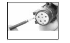
Insertion Tool No insertion tool is required. The contact is easily snapped in from the rear of the connector manually.
- Move to the rear of the connector so that the contact cavities can be identified.
Extraction
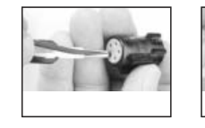
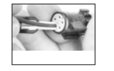
- Open the CET - SLC Extraction
- Using a straight motion forward,
tool and place it over the insulation
insert the tool along the wire until it
of the wire.
bottoms against the connector. (Do not use a screwing motion - damage will result.)
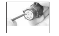
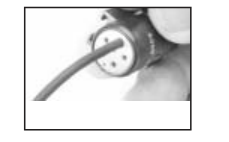
- Insert a crimp terminated
- Continue the forward movement
assembly into a selected cavity.
until and audible snap can be felt and heard. Slight pull in the opposite direction will confirm complete insertion.
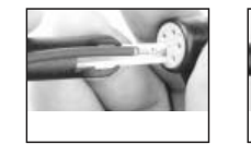
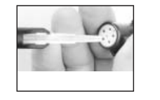
- While the extraction tool is in
- Remove the extraction tool.
place, simply pull the wire/contact
Extraction is complete.
assembly out.
Page 13
Hand Crimp Tool Operation
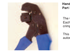
Hand Crimp Tool - CCT - SLC / SLE Part Number: 995-0002-232
The CCT-SLC/SLE hand crimp tool is designed to crimp individual SLC/SLE contacts on wire sizes 16, 18, and 20 AWG. Each cycle is ratchet-controlled (The tool must be completely closed before it can be reopened) to assure a satisfactory crimp each time. Over and under crimps are eliminated.
This tool is for use when the requirement is for low to moderate volume quantities, and for on-site applications where semiautomatic tools cannot be practically used.
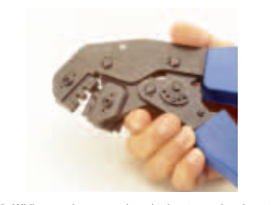
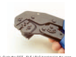
- Cycle the CCT - SLE / SLC hand tool to the open
- While pressing upward on the locator spring, insert
position.
the contact with tails upward completely into the locator.
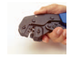
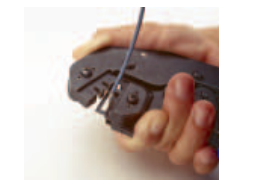
- Partially (usually the first click) Cycle the hand tool 5. Insert the pre-stripped wire into the crimp area of assuring that the upward thrusting tails of the contact the contact and completely cycle the tool. has started engaging with the top jaw of the tool. (There is a slight tendency for the contact to roll out of vertical alignment.)
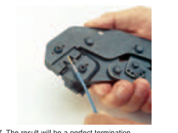
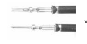
- The result will be a perfect termination.
- Note that there are no unterminated wire strands, and that some strand ends can be seen at the forward edge of the crimp. Also note the insulation is gripped by the smaller secondary crimp. Distortion is at a minimum, both axially and laterally - no sharp edges.
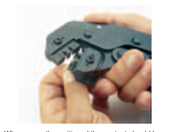
- When correctly positioned the contact should be located beyond flush with the edge of the CCT - SLE / SLC and positioned in the concave polished split level crimp.
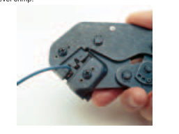
- While pressing upward on the locator spring withdraw the crimp termination.
Wire Stripping
5 and 13 A Contact
B
A
Tolerance
5,33 (.210)
2,41 (.095)
Low
5,59 (.220)
3,30 (.130)
High
Page 14
Lease Automatic Tooling - North America\*
ABT-607 Pneumatic Crimper
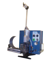
The ABT-607 is a pneumatic powered and controlled machine. It is designed for customers with moderate volume. This machine is designed to semiautomatically crimp stamped and formed contacts onto pre-stripped stranded or single conductor electrical wire. This machine will accommodate size 34 thru 12 AWG wire and is actuated by the use of a foot pedal.
ABT-500 UCCD
The ABT-500 Universal Cannon Crimp Die, is a
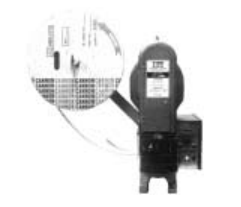
flywheel driven, electronically controlled machine that is designed to semi-automatically crimp stamped and formed contacts on stranded or single conductor, prestripped wire. This machine will accommodate size 34 thru 12 WG wire. The machine is actuated by the use of a foot pedal.
ABT-620 UCCS
The ABT-620 Universal Cannon Crimper/Stripper is a pneumatic powered, microprocessor controlled machine. It is designed to semi-automatically strip insulation from stranded or single conductor electrical wire and attach a stamped and formed contact by crimping. The machine will accommodate 34 thru 12 AWG wire. Primary application of the machine is the termination of jacketed cable where the individual leads cannot be stripped by fully automated equipment. The ABT-620 UCCS operates automatically upon insertion of a wire or it can be switched over to foot pedal operation if desired.
\* For other geographical regions, contact Cannon for details.
Machine Crimp Rate: 800 per hour
Power Requirements: Pneumatic = 100 psi, 2 cu. ft. per min.
Machine Crimp Rate: 1300 per hour
Power Requirements: Electrical = 115VAC, 60Hz, 20A
Machine Crimp Rate: 1200+ per hour
Power Requirements: Electrical = 115VAC, 60Hz, 20A Pneumatic = 80 psi, 3 cu. ft. per min.
Page 15
Crimp Pot Cross Section
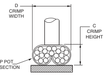
Crimp Height and Width
Wire Gauge (AWG)
CRIMP POT
18
20
16
CROSS SECTION
D Ref.
C\* D Ref.
C\* D Ref.
C\*
Signal (5A)
.064\*
.082
.056\* .080
.054\* .080
Power (13A)
.066\*
.082
.062\* .080
.058\* .080
The wire crimp heights listed are only
\* Hand Tools are ± .002 and machines are ± .001
reference and valid for the correspondingly listed wire size, wire plating and wire stranding.
The wire crimp tensile values must be used to assure the performance of
Insulation Height and Width
crimped contacts.
Wire Gauge (AWG)
18
20
16
For wire crimp information not listed in
Width
Height Width
Height Width
Height
this table, please contact Cannon.
Max
Max\*\*
Max Max\*\*
Max Max\*\*
Signal (5A)
.110
.115\*\*
.105 .110\*\*
.105 .110\*\*
Power (13A)
.110
.115\*\*
.105 .110\*\*
.105 .110\*\*
\*\* Measurements are taken without crimping wire insulation.
Crimp Tensile Strength
Wire Trim Dimension
(.220 - .210)
(.130 - .095)
20
18
16
Wire Size (AWG)
20lbs.
25 lbs.
35 lbs.
Tensile Min (lbs)
Page 16
Test Parameters
SLC Products are designed to meet Cannon specifications CS-206, CS-210, and CS-216. Items of most general interest to users are designers are listed below.
| Test Description | Reference Paragraph | Requirements |
|---|---|---|
| Environmental Sealing | 3.2.3.5 3.2.3.6 3.2.3.7 3.2.3.8 3.2.3.9 3.2.3.2 | Sand and Dust MIL-STD-202 Method 110 Test Condition A 5% salt spray 96 hours 10 cycles of 24 hours, 90-98% humidity Steam Cleaning/Pressure Wash 95°C, 375 Cycles 750 PSIG Solvent Resistance/Immersion (see 3.2.3.9) Thermal Shock 100 Cycles -40°C to +150°C ± 3°C |
| Contact Crimp Tensile Strength | 3.2.2.1 | The minimum tensile load required to separate the wire from the contact, either by pulling the wire out of the crimp joint or by breaking the wire within the crimp joint shall not be less than the applicable limits as specified. Wire breakage or contact damage not due to crimping at less than tensile loads shall not constitute a failure. Wire Size AWG Crimp Tensile Strength, Pounds Minimum 16 35 18 25 20 20 |
| Insulation Resistance | 3.2.1.1 | Mated and wired connectors shall exhibit an insulation resistance greater than 100 megohms between all contacts. This limit shall apply after exposure to each environment including salt solution immersion. Tests shall be performed at 100 VDC ± 10%. |
| Dielectric Withstanding Voltage | 3.2.1.2 | Wired and mated connectors shall show no evidence of breakdown between adjacent contacts when tested at 1000 VDC ± 5%. Connectors shall meet this requirement after exposure to each environment. Current leakage shall be less than 1.0 milliamp. |
| Low Level Contact Resistance | 3.2.1.4 | The low level contact resistance of mated contacts shall be less than 10 milliohms when measured across the contacts and crimp joints. The test current shall be a maximum of 100 milliamps with an open circuit test voltage of 20 millivolts maximum. |
| Mechanical Shock | 3.2.3.3 | Connectors shall be subjected to three shocks in each direction applied along the three mutually perpendicular axes of the connector test specimen for a total of 12 shocks. Each shock shall consist of a terminal peak sawtooth pulse with a peak value of 100 g's and a duration of 6 milliseconds. |
| Vibration | 3.2.3.4 | Connectors shall be subjected to random vibration in accordance with MIL-STD-1344, Method 2005.1, test condition VI for 20 hours along each of the following three axes: Direction Grms Radial axis of connector (Y) 10.2 Longitudinal axis of connector (Z) 10.2 Electrical continuity of the connectors shall be monitored during the last 20 minutes sweep in each axis with a test current of 100 milliamps or less and a test voltage less than 2VDC. Electrical discontinuities in excess of 10 microseconds shall be cause of failure. |
| Durability | 3.2.2.6 | Connectors shall be subjected to 25 cycles of mating and unmating at room temperature. Following this test there shall be no evidence of damage to the contacts, contact plating, connector housing or seals which may prove detrimental to reliable performance of the connector. |
| Contact | 3.2.2.2 | Contacts shall not be displaced greater than 0.030 inches from the connector body when a force of 10 pounds is applied. When this test follows maintenance again the same contacts shall be tested. |
| Maintenance Aging | 3.2.2.3 | Consist of subjecting each wired receptacle to 5 cycles of removal and reinsertion of 20% of the contacts or a minimum of 5 per connector with approved tooling. |
| Mating and Separating Force | 3.2.2.4 | The maximum force required to mate the plug and receptacle shall be 10 pounds. The maximum force required to separate the plug and receptacle shall be 5 pounds. The rate of travel shall be one inch per minute. |
| Solvent Resistance Immersion | 3.2.2.9 | Connectors shall be subjected to the following fluids at the temperature and length of time specified. Following the fluid dip or immersion, the connectors shall be immersed to a depth of 2 to 12 inches in a 5% salt-water solution for 24 hours at room temperature. At the completion of the salt-water immersion test, while still immersed, the connectors shall meet the insulation resistance requirement specified herein. Fluid Method Temperature No. 2 Diesel Fluid Immersion (2) 140°F Methyl Alcohol Dip (1) Room Temperature Antifreeze - Prestone Immersion (2) 180°F - 50% Water/50% Immersion (2) 180°F Ethylene Glycol Degreaser - Gunk Dip (1) Room Temperature - Mineral Spirits Dip (1) Room Temperature Paint (Oil Base) Immersion (2) Room Temperature Lubricating Oil Immersion (2) 200°F (SAE 10 W40) Brake Fluid Dip (1) Room Temperature (Delco Supreme) Transmission Fluid Dip (1) Room Temperature fully submerged and pressurized @ 7 psi. (Dextron) (1) Dip: Connectors shall withstand a one second dip and a three minute air dry for a total of 80 cycles. (2) Immersion: Connectors shall withstand immersion for one hour. |
| Temperature Life | 3.2.3.1 | Connectors shall be subjected to a temperature of 150°C ± 3°C for a period of 1000 hours. At the end of the temperature soak period and after removal from the chamber, the connectors shall meet the insulation resistance and dielectric withstanding voltage requirements specified herein. Connectors shall be operated at rated current throughout the duration of the temperature life test. Upon removal from the chamber at the conclusion of the test, the connectors shall show no visual signs of damage, which may be detrimental to the performance of the connector. |
| Thermal Cycling | 3.2.3.2 | Connectors shall be subjected to 100 thermal cycles from -40°C to +150°C. One cycle shall consist of the transitions from room temperature to -40°C to +150°C, and from 150°C to room temperature. One cycle shall be accomplished in a three-hour period with a minimum stabilization period of 15 minutes at each temperature extreme. The chamber temperature transition rate shall be a minimum of 1.30°C per minute and a maximum of 6.00°C per minute. |
