

 Download PDF
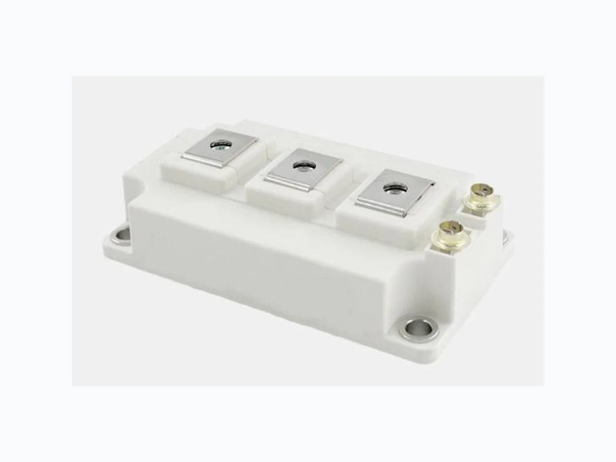
SKM400GM17E4 ISC
Document overview
- Manufacturer or author: Provided By www.digicamel.com(free datasheet download site)
- PDF pages: 5
Technical content
www.iscsemi.com 1
DESCRIPTION
- LowVCE(sat)
- Forswitchingfrequencies upto 8kHz
- WithintegratedGateresistor
APPLICATIONS
- Matrix Inverter
- Bidirectionalswitch MAXIMUM RATEDVALUES(TC=25℃ unless otherwisespecified) SYMBOL PARAMETER VALUE UNIT IGBT VCES Collector-EmitterVoltage 1700 V VGES Gate-EmitterVoltage ±20 V IC CollectorCurrent-ContinuousTC =25℃ 614 A IC CollectorCurrent-ContinuousTC =80℃ 474 A ICM PulsedCollectorCurrent 1200 A tpsc VCC =1000V,VGE ≤ 15V,VCES ≤ 1700V,TJ =150℃ 10 us Tvjop Temperatureunderswitchingconditions -40~+175 ℃ Inversediode VRRM Repetitivepeakreversevoltage 1700 V IF ContinuousDCforwardcurrent TC =25℃ 443 A TC =80℃ 327 IFRM Repetitivepeakforwardcurrent 800 A IFSM tp =10ms,sin180°,Tj =25 ℃ 2340 A
www.iscsemi.com 2 Module It(RMS) 500 A Tstg Storagetemperature -40~+125 ℃ VISOL Isolationtestvoltage RMS, f=50Hz,t=1min. 4000 V ELECTRICALCHARACTERISTICS(TC=25℃ unless otherwise specified) SYMBOL PARAMETER CONDITIONS MIN TYP MAX UNIT ICES Collector-emittercutoffcurren VGE =0V,VCE =1700V -- -- 5 mA VGE(TH) Gate-EmitterThresholdVoltage VGE=20V,IC=16mA 5.2 5.80 6.4 V VCE(sat) Collector-EmitterSaturationVoltage IC=400A,VCE=15V, Tj=25℃ -- 1.92 2.2 V IC=400A,VCE=15V, Tj=150℃ -- 2.3 2.6 Cies InputCapacitance VGS =0V, VCS =25V, f=1.0MHz -- 36 -- nFCOes OnputCapacitance -- 1.36 -- Cres ReverseTransferCapacitance -- 1.16 -- QG GateCharge VGE=-8...+15V -- 3200 -- uC Rthj-c ThermalResistance,JunctiontoCasePerIGBT -- -- 0.066 ℃/W SWITCHINGCHARACTERISTICS(TC=25℃ UNLESSOTHERWISESPECIFIED) SYMBOL PARAMETER CONDITIONS MIN TYP MAX UNIT td(on) Turn-onDelayTime VGE = ±15V, IC=400A, VCE =1200V, RG=2Ω Roff =1Ω di/dton=10000A/µs di/dtoff=2300A/µs dv/dt=5600V/µs TJ=150℃ -- 280 -- ns tr Turn-onRiseTime -- 45 -- td(off) Turn-offDelayTime -- 760 -- tf Turn-offFallTime -- 140 -- Eoff Turn-offswitchinglosses -- 180 -- mJ
www.iscsemi.com 3 Inverse diode SYMBOL PARAMETER CONDITIONS MIN TYP MAX UNIT VF DiodeForwardVoltage V VF0 chiplevel TJ=25℃ 1.32 1.56 TJ=150℃ 1.08 1.22 Irr Peakreverserecoverycurrent VR=1200V, IF=400A, VGE =-15V TJ=150℃ -- 615 -- A Qrr Reverserecoverycharge -- 150 -- uC Erec Reverserecoveryenergy -- 1130 -- mJ Rthj-c ThermalResistance,JunctiontoCase Diode -- -- 0.13 ℃/W MODULE SYMBOL PARAMETER MIN TYP MAX UNIT LsCE Strayinductancemodule -- 15 -- nH RCC'+EE' Moduleleadresistance,terminals-chipTC=25℃ -- 0.55 -- mΩ RCC'+EE' Moduleleadresistance,terminals-chipTC=125℃ -- 0.85 -- mΩ M Mountingtorqueformodulmounting 3.0 -- 5.0 Nm M Terminalconnectiontorque 2.5 -- 5.0 Nm G Weight -- -- 325 g
www.iscsemi.com 4 INTERNALCIRCUIT: PACKAGEOUTLINE(UNIT:mm)
www.iscsemi.com 5 PRODUCTDISCLAIMER ISCreserves the rightstomake changes ofthe contentherein the datasheetat anytimewithout notification.The information containedherein ispresented only asaguide forthe applicationsof our products. ISCproductsareintendedforusageingeneralelectronicequipment.Theproductsarenotdesignedfor usein equipment whichrequire specialized quality and/orreliability,orinequipmentwhichcouldhave applicationsin hazardous environments,aerospaceindustry,ormedicalfield.Pleasecontactus ifyou intend ourproducts to beusedin thesespecial applications. ISCmakes no warrantyor guaranteeregardingthe suitabilityof itsproducts forany particularpurpose, nordoes ISCassumeany liability arisingfromthe application oruse ofany products,and specifically disclaimsanyand allliability,including without limitationspecial,consequentialorincidentaldamages.