


 Download PDF
DATASHEET SEARCH SITE
Document overview
- PDF pages: 2
Technical content
Page 1
SKL12 ... SKL110
SKL12 ... SKL110
SMD Schottky Barrier Rectifier Diodes SMD Schottky-Gleichrichterdioden
Version 2015-12-21
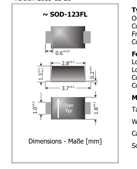
Typical Applications
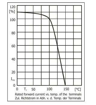
IFAV = 1 A
VRRM = 20...100 V
VF1 < 0.55 V IFSM = 22/25 A
Tjmax = 150°C
Typische Anwendungen
Output Rectification in DC/DC
Ausgangsgleichrichtung in
Converters, Polarity Protection, Free-wheeling diodes Commercial grade 1)
Features
Low forward voltage drop Low profile package
Gleichstromwandlern, Verpolschutz,
Freilaufdioden Standardausführung 1)
Besonderheiten
Halogen
Niedrige Fluss-Spannung
FREE
Flache Bauform
Compliant to RoHS, REACH, Conflict Minerals 1)
Mechanical Data 1)
Taped and reeled
Weight approx.
Case material
Konform zu RoHS, REACH,
Pb
Konfliktmineralien 1)
Mechanische Daten 1)
3000 / 7“
Gegurtet auf Rolle
0.02 g
Gewicht ca.
UL 94V-0
Gehäusematerial
Solder & assembly conditions
260°C/10s
Löt- und Einbaubedingungen
MSL = 1
Maximum ratings 2)
Grenzwerte 2)
Surge peak reverse voltage
Type Repetitive peak reverse voltage
Average forward rectified current
Stoßspitzensperrspannung
Typ
Periodische Spitzensperrspg.
Dauergrenzstrom in Einwegschaltung
VRRM [V]
VRSM [V]
IFAV [A]
at/bei TT [°C]
SKL12
20
20
1
100
SKL13
30
30
1
100
SKL14
40
40
1
100
SKL15
50
50
1
100
SKL16
60
60
1
100
SKL18
80
80
1
100
SKL110
100
100
1
100
| Repetitive peak forward current – Periodischer Spitzenstrom f > 15 Hz | I FRM | 4 A 3) |
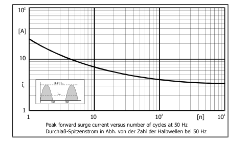
| Peak forward surge current(half sine) – Stoßstrom (Sinus-Halbw.) 50/60 Hz T = 25°C A | I FSM | 22/25 A |
| Rating for fusing, t < 10 ms – Grenzlastintegral, t < 10 ms T = 25°C A | i2t | 2.4 A2s |
| Operating junction temperature – Sperrschichttemperatur Storage temperature – Lagerungstemperatur | T j T S | -50...+150°C -50...+150°C |
Characteristics
Kennwerte
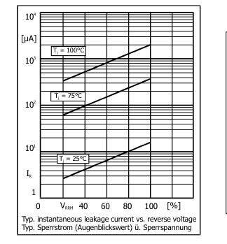
| Leakage current T = 25°C V = V j R RRM Sperrstrom T = 100°C V = V j R RRM | I R I R | < 200 µA typ. 2.0 mA |
|---|---|---|
| Thermal resistance junction to ambient air – Wärmewiderstand Sperrschicht – umgebende Luft Thermal resistance junction to terminal – Wärmewiderstand Sperrschicht − Anschluss | R thA R thT | < 110 K/W 4) < 40 K/W |
1 Please note the detailed information on our website or at the beginning of the data book Bitte beachten Sie die detaillierten Hinweise auf unserer Internetseite bzw. am Anfang des Datenbuches Tj = 25°C unless otherwise specified – Tj = 25°C wenn nicht anders angegeben Max. temperature of the terminals TT = 100°C – Max. Temperatur der Anschlüsse TT = 100°C Mounted on P.C. board with 25 mm2 copper pads at each terminal Montage auf Leiterplatte mit 25 mm2 Kupferbelag (Lötpad) an jedem Anschluss
http://www.diotec.com/
© Diotec Semiconductor AG
Page 2
Characteristics
Type
Forward voltage
Typ
Durchlass-Spannung
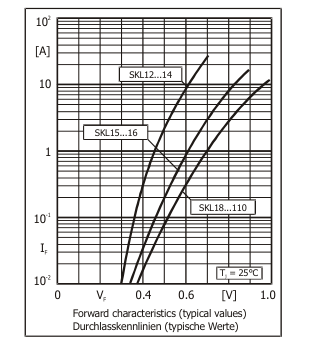
VF [V] @ IF [A]
SKL12 ... SKL14
< 0.55
1
SKL15, SKL16
< 0.70
1
SKL18, SKL110
< 0.85
1
SKL12 ... SKL110
Kennwerte
Junction capacitance
Sperrschichtkapazität
@ Tj
Cj [pF]
@ VR [V]
25°C
typ. 90
6
25°C
typ. 90
6
25°C
typ. 45
6
Disclaimer: See data book page 2 or website
Haftungssauschluss: Siehe Datenbuch Seite 2 oder Internet
http://www.diotec.com/
© Diotec Semiconductor AG