
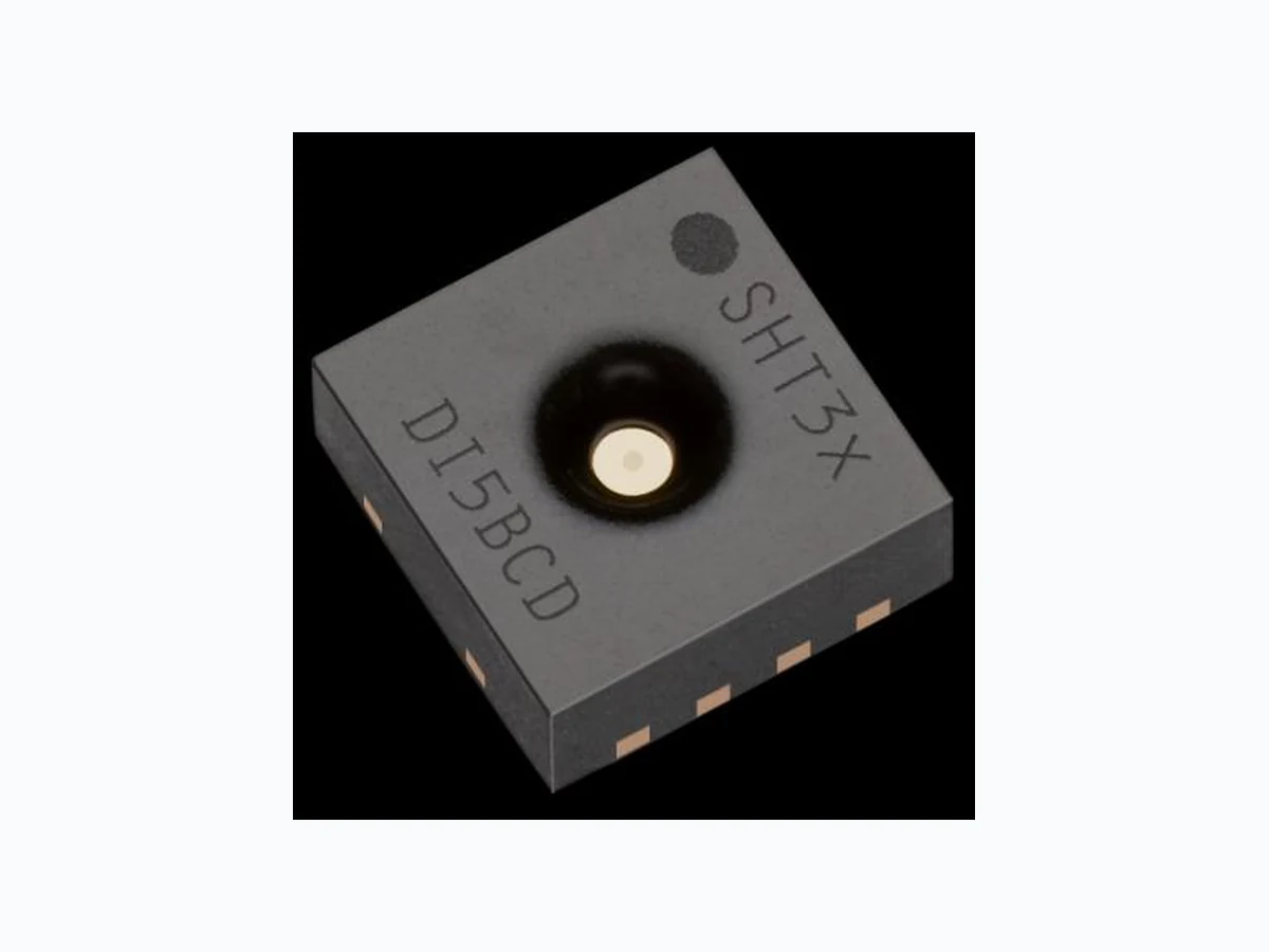
SHT3X-DIS ETC2
Document overview
- Manufacturer or author: Provided By www.digicamel.com(FREE DATASHEET DOWNLOAD SITE)
- PDF pages: 18
Technical content
www.sensirion.com October 2015 - Version 1 1/18 Datasheet SHT3x-DIS Humidity and Temperature Sensor Fully calibrated , linearized, and temperature compensated digital output Wide supply voltage range, from 2.4 V to 5.5 V I2C Interface with communication speeds up to 1 MHz and two user selectable addresses Typical accuracy of 2 %RH and 0.3 °C Very fast start-up and measurement time Tiny 8-Pin DFN package Product Summary SHT3x-DIS is the next generation o f Sensirion’s temperature and humidity sensors . It builds on a new CMOSens® sensor chip that is at the heart of Sensirion’s new humidity and temperature platform. The SHT3x-DIS has increased intelligence, reliability and improved accuracy specifications compared to its predecessor. Its functionality includes enhanced signal processing, two distinctive and user selectable I2C addresses and co mmunication speeds of up to 1 MHz . The DFN package has a footprint of 2.5 x 2.5 mm2 while keeping a height of 0.9 mm. This allows for integration of the SHT3x-DIS into a great variety of applications. Additionally, the wide supply voltage range of 2.4 V to 5.5 V guarantees compatibility with diverse assembly situations . All in all, the SHT3x-DIS incorporates 15 years of knowledge of Sensirion, the leader in the humidity sensor industry. Benefits of Sensirion’s CMOSens® Technology High reliability and long-term stability Industry-proven technology with a track record of more than 15 years Designed for mass production High process capability High signal-to-noise ratio Content Figure 1 Functional block diagram of the SHT3x-DIS. The sensor signals for humidity and temperature are factory calibrated, linearized and compensated for temperature and supply voltage dependencies. nRESET AlertSDA SCLADDR Power on Reset Alert Logic RESET Digital Interface RH Sensor T Sensor Data processing & Linearization ADCADC Calibration Memory VSS VDD VSS VDD
www.sensirion.com October 2015 - Version 1 2/18
1 Sensor Performance
Humidity Sensor Specification Parameter Conditions Value Units SHT30 Accuracy tolerance1 Typ. 3 %RH Max. Figure 2 - SHT31 Accuracy tolerance1 Typ. 2 %RH Max. Figure 3 - Repeatability2 Low 0.25 %RH Medium 0.15 %RH High 0.10 %RH Resolution Typ. 0.01 %RH Hysteresis at 25°C 0.8 %RH Specified range3 extended4 0 to 100 %RH Response time5 63% 86 s Long-term drift Typ.7 <0.25 %RH/yr Table 1 Humidity sensor specification Temperature Sensor Specification Parameter Condition Value Units SHT30 Accuracy tolerance1 typ., 0°C to 65°C 0.3 °C SHT31 Accuracy tolerance1 typ., -40°C to 90°C 0.3 °C Repeatability2 Low 0.24 °C Medium 0.12 °C High 0.06 °C Resolution Typ. 0.015 °C Specified Range - -40 to 125 °C Response time 8 63% >2 s Long Term Drift max <0.03 °C/yr Table 2 Temperature sensor specification. 1 For definition of typical and maximum accuracy tolerance, please refer to the document “Sensirion Humidity Sensor Specification Statement”. 2 The stated repeatability is 3 times the standard deviation (3σ) of multiple consecutive measurements at the stated repeatability and at constant ambient conditions. It is a measure for the noise on the physical sensor output. Different measurement modes allow for high/medium/low repeatability. 3 Specified range refers to the range for which the humidity or temperature sensor specification is guaranteed. 4 For details about recommended humidity and temperature operating range, please refer to section 1.1. 5 Time for achievi ng 63% of a humidity step function, valid at 25°C and 1m/s airflow. Humidity response time in the application depends on the design-in of the sensor. 6 With activated ART function (see section 4.7) the response time can be improved by a factor of 2. 7 Typical value for operation in normal RH/T operating range , see section 1.1. Maximum value is < 0.5 %RH/yr. Higher drift values might occur due to contaminant environments with vaporized solvents, out-gassing tapes, adhesives, packaging materials, etc. For more details please refer to Handling Instructions. 8 Temperature response time s strongly depend on the type of heat exchange, the available sensor surface and the design environment of the sensor in the final application.
www.sensirion.com October 2015 - Version 1 4/18
1.1 Recommended Operating Condition
The sensor shows best performance when operated within recommended normal temperature and humidity ran ge of 5 °C – 60 °C and 20 %RH – 80 %RH, respectively. Long-term exposure to conditions outside normal range, especially at high humidity, may temporarily offset the RH signal (e.g. +3%RH after 60h kept at >80%RH). After returning into the normal temperatur e and humidity range the sensor will slowly come back to calibration state by itself. Prolonged exposure to extreme conditions may accelerate ageing. To ensure stable operation of the humidity sensor, the conditions described in the document “SHTxx Assembly of SMD Packages”, section “Storage and Handling Instructions” regarding exposure to volatile organic compounds have to be met. Please note as well that this does apply not only to transportation and manufacturing, but also to operation of the SHT3x-DIS.
2 Specifications
2.1 Electrical Specifications
Parameter Symbol Condition Min. Typ. Max. Units Comments Supply voltage VDD 2.4 3.3 5.5 V Power-up/down level VPOR 2.1 2.3 2.4 V Slew rate change of the supply voltage VDD,slew - - 20 V/ms Voltage changes on the VDD line between VDD,min and VDD,max should be slower than the maximum slew rate; faster slew rates may lead to reset; Supply current IDD idle state (single shot mode) - 0.2 2.0 A Current when sensor is not performing a measurement during single shot mode idle state (periodic data acquisition mode) - 45 70 A Current when sensor is not performing a measurement during periodic data acquisition mode Measuring - 800 1500 A Current consumption while sensor is measuring Average - 2 5 A Current consumption (operation with one measurement per second at lowest repeatability, single shot mode) Alert Output driving strength IOH 0.8x VDD 1.5x VDD 2.1x VDD mA See also section 3.5 Heater power PHeater Heater running 5 - 25 mW Depending on the supply voltage Table 3 Electrical specifications, valid at 25°C.
www.sensirion.com October 2015 - Version 1 5/18
2.2 Timing Specification for the Sensor System
Parameter Symbol Conditions Min. Typ. Max. Units Comments Power-up time tPU After hard reset, VDD ≥ VPOR - 0.5 1 ms Time between VDD reaching VPOR and sensor entering idle state Soft reset time tSR After soft reset. - 0.5 1 ms Time between ACK of soft reset command and sensor entering idle state Duration of reset pulse tRESETN 350 - - ns See section 3.6 Measurement duration tMEAS,l Low repeatability - 2.5 4 ms The three repeatability modes differ with respect to measurement duration, noise level and energy consumption. tMEAS,m Medium repeatability - 4.5 6 ms tMEAS,h High repeatability - 12.5 15 ms Table 4 System timing specification, valid from -40 °C to 125 °C and 2.4 V to 5.5 V.
2.3 Absolute Minimum and Maximum Ratings
Stress levels beyond those listed in Table 5 may cause permanent damage to the device or affect the reliability of the sensor. These are stress ratings only and functional operation of the device at these conditions is not guaranteed. Parameter Rating Units Supply voltage VDD -0.3 to 6 V Max Voltage on pins (pin 1 (SDA); pin 2 (ADDR); pin 3 (ALERT); pin 4 (SCL); pin 6 (nRESET)) -0.3 to VDD+0.3 V Input current on any pin ±100 mA Operating temperature range -40 to 125 °C Storage temperature range -40 to 150 °C ESD HBM (human body model)9 4 kV ESD CDM (charge device model)10 750 V Table 5 Minimum and maximum ratings; values may only be applied for short time periods. 9 Sensor in application configuration (pin 7 connected to VSS). ESD HBM 2 kV according to JEDEC JS-001. 10 According to JEDEC JS-002.
www.sensirion.com October 2015 - Version 1 6/18
3 Pin Assignment
The SHT3x-DIS comes in a tiny 8-pin DFN package – see Table 6. Pin Name Comments
1 SDA Serial data; input / output
2 ADDR Address pin; input; connect to either
VDD or VSS, do not leave floating
3 ALERT Indicates alarm condition; output; must
be left floating if unused
4 SCL Serial clock; input / output
5 VDD Supply voltage; input
6 nRESET Reset pin active low; input; if not used it is recommended to connect to VDD
7 R No electrical function; to be connected to
8 VSS Ground
Table 6 SHT3x-DIS pin assignment ( transparent top view). Dashed lines are only visible if viewed from below . The die pad is internally connected to VSS.
3.1 Power Pins (VDD, VSS)
The electrical specifications of the SHT3x-DIS are shown in Table 3. The power supply pins must be decoupled with a 100 nF capacitor that shall be plac ed as close to the sensor as possible – see Figure 8 for a typical application circuit.
3.2 Serial Clock and Serial Data (SCL, SDA)
SCL is used to sync hronize the communication between microcontroller and the sensor. The clock frequency can be freely chosen between 0 to 1000 kHz. Commands with clock stretching according to I2C Standard11 are supported. The SDA pin is used to transfer data to and from the sensor. Communication with frequencies up to 400 kHz must meet the I2C Fast Mode 11 standard. Communication frequencies up to 1 Mhz are supported following the specifications given in Table 20. http://www.nxp.com/documents/user_manual/UM10204.pdf Both SCL and SDA lines are open -drain I/Os with diodes to VDD and VSS. They should be connected to external pull -up r esistors (please refer to Figure 8). A device on the I2C bus must only drive a line to ground. The external pull-up resistors (e.g. Rp=10 k Ω) are required to pull the signal high. For dimensioning resistor sizes please take bus capacity and communication frequency into account (see for example Section 7.1 of NXPs I2C Manual for more details11). It should be noted that pull -up resistors may be included in I/O circuits of microcontrollers. It is recommended to wire the sensor ac cording to the application circuit as shown in Figure 8. Figure 8 Typical application circuit. Please note that the positioning of the pins does not reflect the position on the real sensor. This is shown in Table 6.
3.3 Die Pad (center pad)
The di e pad or center pad is visible from below and located in the center of the package. It is electrically connected to VSS. Hence e lectrical considerations do not impose constraints on the wiring of the die pad. However, due to mechanical reasons it is recommended to solder the center pad to the PCB. For more information on design -in, please refer to the document “SHTxx Design Guide”.
3.4 ADDR Pin
Through the appropriate wiring of the ADDR pin the I2C address can be selected (see Table 7 for the respective addresses). Aside from hard wiring the ADDR pin to VDD or VSS, it is also possible to use it as a selector pin. This means that the address of the sensor can be changed dynamically during operation by switching the level on the ADDR pin. The only constraint is that the level has to stay constant starting from the I2C start condition until the communication is finished. This allows to connect mor e than two SHT3x-DIS onto the same bus. The dynamical switching requires individual ADDR lines to the sensors. Please note that the I2C address is represented through the 7 MSBs of the I2C read or write header. 4 5 VDD RRPP 100nF ADDR(2) ALERT(3) die pad R(7) SDA(1) SCL(4) VDD(5) VSS(8) nRESET(6)
Figure 8. The ADDR pin must not be left floating. header constitute the I2C Address. SHT3x-DIS I2C Address in Hex.
3.5 ALERT Pin
occur, depending on the amount of current that fl ows. used to switch a transistor. recommended to connect to VDD.
4 Operation and Communication
refer to NXP I2C-bus specification12. is left to the master to read and process the checksum.
4.1 Power-Up and Communication Start
power-up threshold voltage V POR specified in Table 3.
4.2 Starting a Measurement
4.3 Measurement Commands for Single Shot
Table 8. They differ with respect to repeatability (low, sensor. This is explained in section 0.
www.sensirion.com October 2015 - Version 1 8/18 Condition Hex. code Repeatability Clock stretching MSB LSB High enabled 0x2C Medium 0D Low 10 High disabled 0x24 Medium 0B Low 16 e.g. 0x2C06: high repeatability measurement with clock stretching enabled Table 8 Measurement commands in single shot mode ( Clear blocks are controlled by the microcontroller, grey blocks by the sensor)
4.4 Readout of Measurement R esults for
After the sensor has completed the measurement, the master can read the measurement results (pair of RH& T) by sending a START condition fo llowed by an I2C read header. The sensor will acknowledge the reception of the read header and send two bytes of data (temperature) followed by one byte CRC checksum and another two bytes of data (relative humidity) followed by one byte CRC checksum. Each byte must be acknowledged by the microcontroller with an ACK condition for the sensor to continue sending data. If the sensor does not receive an ACK from the master after any byte of data, it will not continue sending data. The sensor will send the tempe rature value first and then the relative humidity value. After having received the checksum for the humidity value a NACK and stop condition should be sent (see Table 8). The I2C master can abort the read transfer with a NACK condition after any data byte if it is not interested in subsequent data, e.g. the CRC byte or the second measurement result, in order to save time. In case the user needs humidity and temperature data but does not want to process CRC data, it is recommended to read the two temperature bytes of data with the CRC byte (without processing the CRC data); after having read the two humidity bytes, the read transfer can be aborted with a with a NACK. No Clock Stretching When a command with out clock stretching has been issued, the sensor responds to a read header with a not acknowledge (NACK), if no data is present. Clock Stretching When a command with clock stretching has been issued, the sensor responds to a read header with an ACK and subsequently pulls down the SCL line. The SCL line is pulled down until the measurement is complete. As soon as the measurement is complete, the senso r releases the SCL line and sends the measurement results.
4.5 Measurement Commands for Periodic
In this mode one issued measurement command yields a stream of data pairs . Each data pair consists of one 16 bit temperature and one 16 bit humidity value (in this order). In periodic mode different measurement commands can be selected. The corresponding 16 bit commands are shown in Table 9. They differ with respect to repeatability (low, medium and high) and data acquisition frequency (0.5, 1, 2, 4 & 10 measurements per second, mps). Clock stretching cannot be selected in this mode. The data acquisition frequency and the repeatability setting influences the measurement duration and the current consumption of the sensor. This is explained in section 0 of this datasheet. If a measurement command is issued, while the sensor is busy with a measurement (measurement durations see Table 4), i t is recommended to issue a break command first (see section 4.8). Upon reception of the break command the sensor will finish the ongoing measurement and enter the single shot mode.
www.sensirion.com October 2015 - Version 1 9/18 Condition Hex. code Repeatability mps MSB LSB High 0.5 0x20 Medium 24 Low 2F High 1 0x21 Medium 26 Low 2D High 2 0x22 Medium 20 Low 2B High 4 0x23 Medium 22 Low 29 High 10 0x27 Medium 21 Low 2A e.g. 0x2130: 1 high repeatability mps - measurement per second Table 9 Measurement commands for periodic data acquisition mode ( Clear blocks are controlled by the microcontroller, grey blocks by the sensor ). N.B.: At the highest mps setting self-heating of the sensor might occur.
4.6 Readout of M easurement Results for
Transmission of the measurement data can be initiated through the fetch data command shown in Table 10. If no measurement data is present the I2C read header is responded with a NACK (Bit 9 in Table 10) and the communication stops. The fetch data command will deliver the same data until a new measurement updates the humidity and temperature values. Command Hex code Fetch Data 0x E0 00 Table 10 Fetch Data command (Clear blocks are controlled by the microcontroller, grey blocks by the sensor)
4.7 ART Command
The ART (accelerated response time) feature can be activated by issuing the command in Table 11. After issuing the ART command the sensor will start acquiring data with a frequency of 4Hz. The ART command is structurally similar to any other command in Table 9. Hence section 4.5 applies for starting a me asurement, section 4.6 for reading out data and section 4.8 for stopping the periodic data acquisition. The ART feature can also be evaluated using the Evaluation Kit EK-H5 from Sensirion. Command Hex Code Periodic Measurement with ART 0x2B32 Table 11 Command for a periodic data acquisition with the ART feature (Clear blocks are controlled by the microcontroller, grey blocks by the sensor).
4.8 Break command / Stop Periodic Data
The periodic data acquisition mode can be stopped using the break command shown in Table 12. It is recommended to stop the periodic data acquisition prior to sending another command (except Fetch Data command) using the break command. Upon reception of the break command the sensor enters the single shot mode, after finishing the ongoing measurement. This can take up to 15 ms, depending on the selected repeatability. Command Hex Code Break 0x3093 Table 12 Break command (Clear blocks are controlled by the microcontroller, grey blocks by the sensor).
4.9 Reset
A system reset of the SHT3x-DIS can be generated externally by issuing a command (soft reset) or by sending a pulse to the dedicated reset pin (nReset pin). Additionally, a system reset is gene rated internally during power-up. During the reset procedure the sensor will not process commands. S ACKWI2C Address 1 2 3 4 5 6 7 8 9 ACKCommand MSB 1 2 3 4 5 6 7 8 9 ACKCommand LSB 10 11 12 13 14 15 16 17 18 16-bit commandI2C write header S ACKWI2C Address 1 2 3 4 5 6 7 8 9 ACKCommand MSB 1 2 3 4 5 6 7 8 9 ACKCommand LSB 10 11 12 13 14 15 16 17 18 16-bit commandI2C write header
www.sensirion.com October 2015 - Version 1 10/18 In order to achieve a full reset of the sensor without removing the power supply, it is recommended to use the nRESET pin of the SHT3x-DIS. Interface Reset If communication with the device is lost, the following signal sequence will reset the serial interface: While leaving SDA high, toggle SCL nine or more times. This must be followed by a Transmission Start sequence preceding the next command. This sequence resets the interface only. The status register preserves its content. Soft Reset / Re-Initialization The SHT3x-DIS provides a soft reset mechanism that forces the system into a well -defined state without removing the power supply. When the system is in idle state the soft reset command can be sent to the SHT3x-DIS. This triggers the sensor to reset its system controller and reloads calibration data from the memory. In order to start the soft reset procedure the command as shown in Table 13 should be sent. It is worth noting that the sensor reloads calibration data prior to every measurement by default. Command Hex Code Soft Reset 0x30A2 Table 13 Soft reset command (Clear blocks are controlled by the microcontroller, grey blocks by the sensor) Reset through General Call Additionally, a reset of the sensor can also be generated using the “general call” mode according to I2C-bus specification12. This generates a reset which is functionally identical to using the nReset pin. It is important to understan d that a reset generated in this way is not device specific. All devices on the same I2C bus that support the general call mode will perform a reset. Additionally, this command only works when the sensor is able to process I2C commands. The appropriate com mand consists of two bytes and is shown in Table 14. Reset through the nReset Pin Pulling the nReset pin low (see Table 6) generates a reset similar to a hard reset. The nReset pin is internally connected to VDD through a pull -up resistor and hence active low. The nReset pin has to be pulled low for a minimum of 350 ns to generate a reset of the sensor. Command Code Address byte 0x00 Second byte 0x06 Reset command using the general call address 0x0006 Table 14 Reset through the general c all address ( Clear blocks are controlled by the microcontroller, grey blocks by the sensor). Hard Reset A hard reset is achieved by switching the supply voltage to the VDD Pin off and then on again. In order to prevent powering the sensor over the ESD diodes, the voltage to pins 1 (SDA), 4 (SCL) and 2 (ADDR) also needs to be removed.
4.10 Heater
The heater can be switched on and off by command, see table below. The status is listed in the status register. After a reset the heater is disabled (default condition). Command Hex Code MSB LSB Heater Enable 0x30 6D Heater Disabled 66 Table 15 Heater command (Clear blocks are controlled by the microcontroller, grey blocks by the sensor)
4.11 Status Register
The status register contains information on the operational status of the heater, the alert mode and on the execution status of the last command and the last write sequence. The command to read out the status register is shown in Table 16 whereas a description of the content can be found in Table 17. S ACKGeneral Call Address 1 2 3 4 5 6 7 8 9 ACKReset Command 1 2 3 4 5 6 7 8 9 General Call 1st byte General Call 2nd byte
www.sensirion.com October 2015 - Version 1 11/18 Command Hex code Read Out of status register 0xF32D Table 16 Command to read out the status register (Clear blocks are controlled by the microcontroller, grey blocks by the sensor) Bit Field description Default value
15 Alert pending status
'0': no pending alerts '1': at least one pending alert ‘1’
14 Reserved ‘0’
13 Heater status
‘0’ : Heater OFF ‘1’ : Heater ON ‘0’
12 Reserved ‘0’
11 RH tracking alert
‘0’ : no alert ‘1’ . alert
10 T tracking alert
‘0’ : no alert ‘1’ . alert ‘0’ 9:5 Reserved ‘xxxxx’
4 System reset detected
'0': no reset detected since last ‘clear status register’ command '1': reset detected (hard reset, soft reset command or supply fail) ‘1’ 3:2 Reserved ‘00’
1 Command status
'0': last command executed successfully '1': last command not processed. It was either invalid, failed the integrated command checksum ‘0’
0 Write data checksum status
'0': checksum of last write transfer was correct '1': checksum of last write transfer failed ‘0’ Table 17 Description of the status register. Clear Status Register All flags (Bit 15, 11, 10, 4) in the status register can be cleared (set to zero) by sending the command shown in Table 18. Command Hex Code Clear status register 0x 30 41 Table 18 Command to clear the status register (Clear blocks are controlled by the microcontroller, grey blocks by the sensor)
4.12 Checksum Calculation
The 8 -bit CRC checksum transmitted after each data word is generated by a CRC algorithm . Its properties are displayed in Table 19. The CRC covers the contents of the two previously transmitted data bytes. To calculate the checksum only t hese two previously transmitted data bytes are used. Property Value Name CRC-8 Width 8 bit Protected data read and/or write data Polynomial 0x31 (x8 + x5 + x4 + 1) Initialization 0xFF Reflect input False Reflect output False Final XOR 0x00 Examples CRC (0xBEEF) = 0x92 Table 19 I2C CRC properties.
4.13 Conversion of Signal Output
Measurement data is always transferred as 16 -bit values (unsigned integer) . These values are alrea dy linearized and compensated for temperature and supply voltage effects. Converting those raw values into a physical scale can be achieved using the following formulas. Relative humidity conversion formula (result in %RH): 16 RH S 100 RH Temperature conversion formula (result in °C & °F): 1 T T S 315 49 F T S 175 45 C T SRH and ST denote the raw sensor output for humidity and temperature, respectively. The formulas work only correctly when S RH and S T are used in decimal representation.
www.sensirion.com October 2015 - Version 1 12/18
4.14 Communication Timing
Parameter Symbol Conditions Min. Typ. Max. Units Comments SCL clock frequency fSCL 0 - 1000 kHz Hold time (repeated) START condition tHD;STA After this period, the first clock pulse is generated 0.24 - - µs LOW period of the SCL clock tLOW 0.65 - - µs HIGH period of the SCL clock tHIGH 0.26 - - µs SDA hold time tHD;DAT 0 - 250 ns Transmitting data 0 - - ns Receiving data SDA set-up time tSU;DAT 100 - - ns SCL/SDA rise time tR - - 300 ns SCL/SDA fall time tF - - 300 ns SDA valid time tVD;DAT - - 0.9 µs Set-up time for a repeated START condition tSU;STA 0.6 - - µs Set-up time for STOP condition tSU;STO 0.6 - - µs Capacitive load on bus line CB - - 400 pF Low level input voltage VIL -0.5 - 0.3xVDD V High level input voltage VIH 0.7xVDD - 1xVDD V Low level output voltage VOL 3 mA sink current - - 0.66 V Table 20 Communication timing specifications for I2C fm (fast mode) , specifications are at 25°C and typical VDD . The numbers above are values according to the I2C Specification (UM10204, Rev. 6, April 4, 2014). Figure 9 Timing diagram for digital input/output pads. SDA directions are seen from the sensor. Bold SDA lines are controlled by the sensor, plain SDA lines are controlled by the micro -controller. Note that SDA valid read time is triggered by falling edge of preceding toggle. SCL 70% 30% tLOW 1/fSCL tHIGH tR tF SDA 70% 30% tSU;DAT tHD;DAT DATA IN tR SDA 70% 30% DATA OUT tVD;DAT tF
www.sensirion.com October 2015 - Version 1 13/18
5 Packaging
SHT3x-DIS sensors are provided in a n open-cavity DFN package. DFN stands for dual flat no leads. The humidity sensor opening is centered on the top side of the package. The sensor chip is made of silicon and is mounted to a lead frame. The latter is made of Cu plated with Ni/Pd/Au. Chip and lead frame are overmolded by a n epoxy-based mold compound leaving the central die pad and I/O pins exposed for mechanical and electrical connection. Please note that the side walls of the sensor are diced and therefore these diced lead frame surfaces are not covered with the respective plating. The package (except for the humidity sensor opening) follows JEDEC publication 95, design registration 4.20, small scale plastic quad and dual inline, square and rectangular, No-LEAD packages (with optional thermal enhancements) small scale (QFN/SON), Issue D.01, September 2009. SHT3x-DIS has a Moisture Sensitivity Level (MSL) of 1, according to IPC/JEDEC J -STD-020. At t he same time, it is recommended to further process the sensors within 1 year after date of delivery.
5.1 Traceability
All SHT3x-DIS sensors are laser marked for easy identification and traceability. The marking on the sensor top side consists of a pin -1 ind icator and two lines of text. The top line consist of the pin-1 indicator which is located in the top left corner and the product name. The small letter x stands for the accuracy class. The bottom line consists of 6 letters. The first two digits XY (=DI) describe the output mode. The third letter (A) represents the manufacturing year (4 = 2014, 5 = 2015, etc). The last three digits (BCD) represent an alphanumeric tracking code. That code can be decoded by Sensirion only and allows for tracking on batch level through production, calibration and testing – and will be provided upon justified request. If viewed from below pin 1 is indicated by triangular shaped cut in the otherwise rectangular die pad. The dimensions of the triangular cut are shown in Figure 11 through the labels T1 & T2. Figure 10 Top View of the SHT3x-DIS illustrating the laser marking. SHT3 x XYABCD
www.sensirion.com October 2015 - Version 1 14/18
5.2 Package Outline
Figure 11 Dimensional drawing of SHT3x-DIS sensor package Parameter Symbol Min Nom. Max Units Comments Package height A 0.8 0.9 1 mm Leadframe height A3 - 0.2 - mm Pad width b 0.2 0.25 0.3 mm Package width D 2.4 2.5 2.6 mm Center pad length D2 1 1.1 1.2 mm Package length E 2.4 2.5 2.6 mm Center pad width E2 1.7 1.8 1.9 mm Pad pitch e - 0.5 mm Pad length L 0.3 0.35 0.4 mm Max cavity S - - 1.5 mm Only as guidance. This value includes all tolerances, including displacement tolerances. Typically the opening will be smaller. Center pad marking T1xT2 - 0.3x45° - mm indicates the position of pin 1 Table 21 Package outline,
5.3 Land Pattern
Figure 12 shows the land pattern. The land pattern is understood to be the open metal areas on the PCB, onto which the DFN pads are soldered. The sold er mask is understood to be the insulating layer on top of the PCB covering the copper traces. It is recommended to design the solder pads as a Non- Solder Mask Defined (NSMD) type. For NSMD pads, the solder mask opening should provid e a 60 μm to 75 μm design clearance between any copper pad and solder mask. As the pad pitch is only 0.5 mm we recommend to have one solder mask opening for all 4 I/O pads on one side. For solder paste printing it is recommended to use a laser-cut, stainless steel stencil with electro -polished trapezoidal walls and with 0.1 or 0.125 mm stencil thickness. The length of the stencil apertures for the I/O pads should be the same as the PCB pads . However, the position of the stencil apertures should have an offset of 0.1 mm away from the center of the package. The die pad aperture should cover about 70 – 90 % of the die pad area –thus it should have a size of about 0.9 mm x 1.6 mm. For information on the soldering process and further recommendation on the ass embly process pleas e consult the Application Note HT_AN_SHTxx_Assembly_of_SMD_Packages , which can be found on the Sensirion webpage.
www.sensirion.com October 2015 - Version 1 15/18 Figure 12 Recommended metal land pattern (left) and stencil apertures (right) for the SHT3x-DIS. The dashed lines represent the outer dimension of the DFN package. The PCB pads (left) and stencil apertures (right) are indicated through the shaded areas.
6 Shipping Package
Figure 13 Technical drawing of the packaging tape with sensor orientation in tape. Header tape is to the right and trailer tape to the left on this drawing. Dimensions are given in millimeters. 1.7 0.25 0.5 0.5 0.5 0.55 0.3x45° 0.375 0.2 0.75 0.4 0.9 1.6 0.55 0.5 0.5 0.5 0.25 0.55 0.45 0.8 0.375 0.3 land pattern stencil aperturesensor outline TOLERANCES - UNLESS NOTED 1PL ±.2 2PL ±.10 A = 2.75 B = 2.75 K = 1.20 NOTES: 1. 10 SPROCKET HOLE PITCH CUMULATIVE TOLERANCE ±0.2 2. POCKET POSITION RELATIVE TO SPROCKET HOLE MEASURED AS TRUE POSITION OF POCKET, NOT POCKET HOLE 3. A0 AND B0 ARE CALCULATED ON A PLANE AT A DISTANCE "R" ABOVE THE BOTTOM OF THE POCKET R 0.25 TYP. SECTION A - A 0.30 ±.05 A R 0.2 MAX. 0.30 ±.05 2.00 ±.05 SEE Note 2 4.00
4.00 SEE Note 1
Ø1.5 +.1 /-0.0 Ø1.00 MIN 1.75 ±.1 12.0 +0.3/-0.1 5.50 ±.05 SEE NOTE 2 A B DETAIL B
www.sensirion.com October 2015 - Version 1 16/18
7 Quality
Qualification of the SHT3x-DIS is performed based on the AEC Q 100 qualification test method.
7.1 Material Contents
The device is fully RoHS and WEEE compliant, e.g. free of Pb, Cd, and Hg.
8 Ordering Information
The SHT3x-DIS can be ordered in tape and reel packaging with different sizes, see Table 22. The reels are sealed into antistatic ESD ba gs. The document “SHT3x shipping package” that shows the details about the shipping package is available upon request. Name Quantity Order Number SHT30-DIS-B2.5kS 2500 1-101400-01 SHT30-DIS-B10kS 10000 1-101173-01 SHT31-DIS-B2.5kS 2500 1-101386-01 SHT31-DIS-B10kS 10000 1-101147-01 Table 22 SHT3x-DIS ordering options.
9 Further Information
For more in-depth information on the SHT3x-DIS and its application please consult the following documents: Document Name Description Source SHT3x Shipping Package Information on Tape, Reel and shipping bags (technical drawing and dimensions) Available upon request SHTxx Assembly of SMD Packages Assembly Guide (Soldering Instructions) Available for download at the Sensirion humidity sensors download center: www.sensirion.com/humidity-download SHTxx Design Guide Design guidelines for designing SHTxx humidity sensors into applications Available for download at the Sensirion humidity sensors download center: www.sensirion.com/humidity-download SHTxx Handling Instructions Guidelines for proper handling of SHTxx humidity sensors Available for download at the Sensirion humidity sensors download center: www.sensirion.com/humidity-download Sensirion Humidity Sensor Specification Statement Definition of sensor specifications. Available for download at the Sensirion humidity sensors download center: www.sensirion.com/humidity-download Table 23 Documents containing further information relevant for the SHT3x-DIS.
www.sensirion.com October 2015 - Version 1 17/18
Revision History
Date Version Page(s) Changes October 2015 1
www.sensirion.com October 2015 - Version 1 18/18 Important Notices Warning, Personal Injury Do not use this product as safety or emergency stop devices or in any other application where failure of the product could result in personal injury. Do not use this product for applications other than its intended and authorized use. Before installing, handling, using or servicing this product, please consult the data sheet and application notes. Failure to comply with these instructions could result in death or serious injury. If the Buyer shall purchase or use SENSIRION products for any unintended or unauthorized application, Buyer shall defend, indemnify and hold harmles s SENSIRION and its officers, employees, subsidiaries, affiliates and distributors against all claims, costs, damages and expenses, and reasonable attorney fees arising out of, directly or indirectly, any claim of personal injury or death associated with s uch unintended or unauthorized use, even if SENSIRION shall be allegedly negligent with respect to the design or the manufacture of the product. ESD Precautions The inherent design of this component causes it to be sensitive to electrostatic discharge (ESD ). To prevent ESD -induced damage and/or degradation, take customary and statutory ESD precautions when handling this product. See application note “ESD, Latchup and EMC” for more information. Warranty SENSIRION warrants solely to the original purchaser of this product for a period of 12 months (one year) from the date of delivery that this product shall be of the quality, material and workmanship defined in SENSIRION’s published specifications of the product. Within such period, if proven to be defective, S ENSIRION shall repair and/or replace this product, in SENSIRION’s discretion, free of charge to the Buyer, provided that: notice in writing describing the defects shall be given to SENSIRION within fourteen (14) days after their appearance; such defects shall be found, to SENSIRION’s reasonable satisfaction, to have arisen from SENSIRION’s faulty design, material, or workmanship; the defective product shall be returned to SENSIRION’s factory at the Buyer’s expense; and the warranty period for any repaired or replaced product shall be limited to the unexpired portion of the original period. This warranty does not apply to any equipment which has not been installed and used within the specifications recommended by SENSIRION for the intended and proper use of the equipment. EXCEPT FOR THE WARRANTIES EXPRESSLY SET FORTH HEREIN, SENSIRION MAKES NO WARRANTIES, EITHER EXPRESS OR IMPLIED, WITH RESPECT TO THE PRODUCT. ANY AND ALL WARRANTIES, INCLUDING WITHOUT LIMITATION, WARRANTIES OF MERCHANTABILITY OR FITNESS FOR A PARTICULAR PURPOSE, ARE EXPRESSLY EXCLUDED AND DECLINED. SENSIRION is only liable for defects of this product arising under the conditions of operation provided for in the data sheet and proper use of the goods. SENSIRION explicitly disclaims all warrant ies, express or implied, for any period during which the goods are operated or stored not in accordance with the technical specifications. SENSIRION does not assume any liability arising out of any application or use of any product or circuit and specifica lly disclaims any and all liability, including without limitation consequential or incidental damages. All operating parameters, including without limitation recommended parameters, must be validated for each customer’s applications by customer’s technical experts. Recommended parameters can and do vary in different applications. SENSIRION reserves the right, without further notice, (i) to change the product specifications and/or the information in this document and (ii) to improve reliability, functions and design of this product. Copyright © 2015, by SENSIRION. CMOSens® is a trademark of Sensirion All rights reserved Headquarters and Subsidiaries Sensirion AG Laubisruetistr. 50 CH-8712 Staefa ZH Switzerland Phone: +41 44 306 40 00 Fax: +41 44 306 40 30 info@sensirion.com www.sensirion.com Sensirion Inc., USA Phone: +1 805 409 4900 info_us@sensirion.com www.sensirion.com Sensirion Japan Co. Ltd. Phone: +81 3 3444 4940 info@sensirion.co.jp www.sensirion.co.jp Sensirion Korea Co. Ltd. Phone: +82 31 337 7700~3 info@sensirion.co.kr www.sensirion.co.kr Sensirion China Co. Ltd. Phone: +86 755 8252 1501 info@sensirion.com.cn www.sensirion.com.cn To find your local representative, please visit www.sensirion.com/contact