
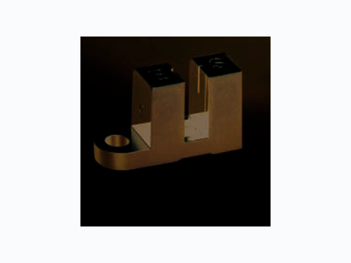
SFH9301 OSRAM
Document overview
- Manufacturer or author: Provided By www.digicamel.com(FREE DATASHEET DOWNLOAD SITE)
- PDF pages: 12
Technical content
Features
Compact type GaAs infrared emitter (950 nm) Silicon phototransistor detector with daylight-cutoff filter Different packages using SFH 4110 and SFH 3100 F as basic components – SFH 9301: without mounting tab, version for automatical assembly available on request – SFH 9302: mounting tab on emitter and sensor side – SFH 9303: mounting tab on sensor side – SFH 9304: mounting tab on emitter side – SFH 9306: without mounting tab, with positioning pins
SFH 9301, SFH 9302, SFH 9303, SFH 9304, SFH 9306 2001-02-22 2 Anwendungen Geschwindigkeitsüberwachung Motorsteuerung Ü berwachung des Papiervorschubs in Druckern, Kopier- und Faxgeräten Speicherlaufwerke Steuerung des Druckkopfes in Druckern M ünzdetektion Optoelektronische Schalter Typ Type Bestellnummer Ordering Code Gehäuse Package SFH 9301 Q62702-P5083 Schwarzes Polykarbonat Plastikgeh äuse, Anschlüsse im 2.54-mm Raster, Senderseite durch Buchstaben „E“, Empfängerseite durch Buchstaben „S“ gekennzeichnet, Kathode / Transistoremitter durch schräge Kante gekennzeichnet. Black polycarbonate plastic material housing, solder tabs 2.54-mm (1/10”) spacing, emitter side marked with letter “E”, sensor side marked with letter “S”, cathode / emitter of transistor marked with edge at an angle. SFH 9302 Q62702-P5084 SFH 9303 Q62702-P5085 SFH 9304 Q62702-P5086 SFH 9306 Q62702-P5130
Applications
Speed control Motor control Monitoring of paper feed in printers, copiers, facsimiles Disk drives Control of print head in printers Coin detection Optoelectronic switches
SFH 9301, SFH 9302, SFH 9303, SFH 9304, SFH 9306 2001-02-22 3 Grenzwerte TA = 25 °C Maximum Ratings Bezeichnung Parameter Symbol Symbol Wert Value Einheit Unit Sender (GaAs-Diode) Emitter (GaAs Diode) Sperrspannung Reverse voltage VR 5V Durchlaßstrom Forward current IF (DC) 60 mA Verlustleistung Power dissipation Ptot 100 mW W ärmewiderstand Thermal resistance RthJA 280 K/W Empf änger (Si-Fototransistor) Detector (Silicon Phototransistor) Kollektor-Emitter-Spannung Collector-emitter voltage VCE 30 V Kollektor-Emitter-Spannung, (t ≤ 2 min) Collector-emitter voltage, (t ≤ 2 min) VCE 70 Emitter-Kollektor-Spannung Emitter-collector voltage VEC 7 Kollektorstrom Collector current IC 50 mA Verlustleistung Total power dissipation Ptot 150 mW W ärmewiderstand Thermal resistance RthJA 280 K/W Gabellichtschranke Slotted Interrupter Lagertemperatur Storage temperature range Tstg – 40… + 85 °C Betriebstemperatur Operating temperature range Top – 40… + 85 Elektrostatische Entladung Electrostatic discharge ESD 2 kV
SFH 9301, SFH 9302, SFH 9303, SFH 9304, SFH 9306 Kennwerte TA = 25 °C Characteristics Bezeichnung Parameter Symbol Symbol Wert Value Einheit Unit Sender (GaAs-Diode) Emitter (GaAs Diode) Wellenlänge der Strahlung Wavelength of peak emission λpeak 950 nm Durchlaβspannung Forward voltage IF = 20 mA, tp = 20 ms VF 1.2 (≤ 1.4) V Sperrstrom Reverse current VR = 5 V IR 0.01 (≤ 1) µA Kapazität Capacitance VR = 0 V, f = 1 MHz C 0 16 pF Empf änger (Si-Fototransistor) Detector (Silicon Phototransistor) Wellenlänge der max. Fotoempfindlichkeit Wavelength of max. sensitivity λS max 920 nm Spectr. Bereich der Fotoempfindlichkeit Spectral range of sensitivity S = 10% of Smax λ 840 … 1080 nm Kapazität Capacitance VCE = 0 V, f = 1 MHz, E = 0 C CE 6.5 pF Dunkelstrom Dark current VCE = 20 V ICEO 2 (≤ 50) nA
SFH 9301, SFH 9302, SFH 9303, SFH 9304, SFH 9306 2001-02-22 5 Gabellichtschranke Slotted Interrupter Kollektor-Emitterstrom Collector-emitter current IF = 20 mA; VCE = 5 V ICE min. ICE typ. > 0.7 mA Kollektor-Emitter-Sättigungsspannung Collector-emitter-saturation voltage IF = 20 mA; IC = 0.2 mA VCE sat ≤ 0.4 V Anstiegs- und Abfallzeit Rise and fall time VCC = 5 V, IC = 1 mA, RL = 1 kΩ tr tf µs µs Kennwerte TA = 25 °C Characteristics (cont’d) Bezeichnung Parameter Symbol Symbol Wert Value Einheit Unit
SFH 9301, SFH 9302, SFH 9303, SFH 9304, SFH 9306 2001-02-22 6 Forward Current IF = f (VF) Single pulse, tp = 20 µs Total Power Dissipation for Emitter and Detector Ptot = f (TA) V OHF00367 F 10-2 ΙF 12340.5 1.5 2.5 V 10-1 100 101 102 103 104 mA T OHF00410 A totP 0 02 0 4 0 60 80 100˚C 100 120 140
160 Detector
Max. Permissible Forward Current IF = f (TA) T OHF00372 A 0 0 ΙF 20 40 60 80 120 mA C R thJA= 280 K/W Dark Current ICEO = f (TA) VCE = 20 V, E = 0 T OHF00380 A CEOΙ -110 10 0 10 1 10 2 10 3 nA 20 40 60 80 100˚C
SFH 9301, SFH 9302, SFH 9303, SFH 9304, SFH 9306 2001-02-22 7 Ma ßzeichnung Package Outlines Ma ße werden wie folgt angegeben: mm (inch) / Dimensions are specified as follows: mm (inch). 3.38 (0.133) 2.98 (0.117) 12.52 (0.493) 12.12 (0.477) 11.0 (0.433) 10.6 (0.417) optical axis 8.2 (0.323) 8.0 (0.315) 6.68 (0.263) 6.28 (0.247) 2.54 (0.100) 9.0 (0.354) 0.25 (0.010) Emitter Sensor GPXY6992 3Circuitry 2.74 (0.108) 2.34 (0.092) 8.0 (0.315) 5.0 (0.197) 0.6 (0.024) 0.5 (0.020) 8.2 (0.323) 0.25 (0.010) 1.27 (0.050) SFH 9301
SFH 9301, SFH 9302, SFH 9303, SFH 9304, SFH 9306 Ma ße werden wie folgt angegeben: mm (inch) / Dimensions are specified as follows: mm (inch). GPXY6993 19.2 (0.756) 18.8 (0.740) 24.85 (0.978) 24.45 (0.963) Emitter Sensor
2 Circuitry
12.52 (0.493) 12.12 (0.477) 3.38 (0.133) 2.74 (0.108) 10.6 (0.417) 11.0 (0.433) 8.0 (0.315) 5.0 (0.197) 8.2 (0.323) 8.0 (0.315) 0.3 (0.012) 0.5 (0.020) optical axis 6.28 (0.247) 6.68 (0.263) 0.25 (0.010) 0.6 (0.024) 8.2 (0.323) 9.0 (0.354) 1.27 (0.050) 0.25 (0.010) 3.28 (0.129) 3.08 (0.121) SFH 9302
SFH 9301, SFH 9302, SFH 9303, SFH 9304, SFH 9306 2001-02-22 9 Ma ße werden wie folgt angegeben: mm (inch) / Dimensions are specified as follows: mm (inch). GPXY6994 Emitter Sensor Circuitry2 1 4 2.74 (0.108) 2.34 (0.092) 3.38 (0.133) 2.98 (0.117) 12.52 (0.493) 12.12 (0.477) 5.0 (0.197) 0.3 (0.012) 0.5 (0.020) 8.2 (0.323) 8.0 (0.315) optical axis 6.28 (0.247) 6.68 (0.263) 9.0 (0.354) 8.2 (0.323) 0.25 (0.010) 0.4 (0.016) 0.6 (0.024) 2.54 (0.100) 3.28 (0.129) 3.08 (0.121) 1.27 (0.050) 0.25 (0.010) 18.75 (0.738) 18.25 (0.719) 15.9 (0.626) 15.4 (0.606) 11.0 (0.433) 8.0 (0.315) 10.6 (0.417) SFH 9303
SFH 9301, SFH 9302, SFH 9303, SFH 9304, SFH 9306 Ma ße werden wie folgt angegeben: mm (inch) / Dimensions are specified as follows: mm (inch). GPXY6995 3.28 (0.129) 3.08 (0.121) 15.9 (0.626) 15.4 (0.606) 18.75 (0.738) 18.25 (0.719) Emitter Sensor Circuitry2 1 4 3.38 (0.133) 2.98 (0.117) 12.52 (0.493) 12.12 (0.477) 10.6 (0.417) 11.0 (0.433) 8.0 (0.315) 5.0 (0.197) 0.3 (0.012) 0.5 (0.020) 8.2 (0.323) 8.0 (0.315) 2.74 (0.108) 2.34 (0.092) 6.28 (0.247) 6.68 (0.263) optical axis 0.6 (0.024) 0.25 (0.010) 8.2 (0.323) 9.0 (0.354) 1.27 (0.050) 0.25 (0.010) SFH 9304
SFH 9301, SFH 9302, SFH 9303, SFH 9304, SFH 9306 2001-02-22 11 Ma ße werden wie folgt angegeben: mm (inch) / Dimensions are specified as follows: mm (inch). GPXY6997 1.1 (0.043) Emitter Sensor 0.9 (0.035) Circuitry2 1 4 12.52 (0.493) 12.12 (0.477) 3.38 (0.133) 2.98 (0.117) 11.0 (0.433) 10.6 (0.417) 8.0 (0.315) 2.34 (0.092) 2.74 (0.108) 5.0 (0.197) 0.5 (0.020) 8.0 (0.315) optical axis 6.68 (0.263) 6.28 (0.247) 0.25 (0.010) 2.54 (0.100) 0.6 (0.024) 0.4 (0.016) 9.0 (0.354) 8.2 (0.323) 1.27 (0.050) 0.25 (0.010) SFH 9306
SFH 9301, SFH 9302, SFH 9303, SFH 9304, SFH 9306 Published by OSRAM Opto Semiconductors GmbH & Co. OHG Wernerwerkstrasse 2, D-93049 Regensburg © All Rights Reserved. Attention please! The information describes the type of component and shall not be considered as assured characteristics. Terms of delivery and rights to change design reserved. Due to technical requirements components may contain dangerous substances. For information on the types in question please contact our Sales Organization. Packing Please use the recycling operators known to you. We can also help you – get in touch with your nearest sales office. By agreement we will take packing material back, if it is sorted. You must bear the costs of transport. For packing material that is returned to us unsorted or which we are not obliged to accept, we shall have to invoice you for any costs incurred. Components used in life-support devices or systems must be expressly authorized for such purpose! Critical components 1 may only be used in life-support devices or systems 2 with the express written approval of OSRAM OS. 1 A critical component is a component used in a life-support device or system whose failure can reasonably be expected to cause the failure of that life-support device or system, or to affect its safety or effectiveness of that device or system. 2 Life support devices or systems are intended (a) to be implanted in the human body, or (b) to support and/or maintain and sustain human life. If they fail, it is reasonable to assume that the health of the user may be endangered. Löthinweise Soldering Conditions Bauform Type Tauch-, Schwalllötung Dip, Wave Soldering Reflowlötung Reflow Soldering Kolbenlötung Iron Soldering Peak Temp. (solderbath) Max. Time in peak zone Peak Temp. (package temp.) Max. Time in Peak Zone (Iron temp.) SFH 930x 260 °C 10 s n. a. – 300 °C < 5 s