
DATASHEET SEARCH SITE
Document overview
- Manufacturer or author: Provided By www.digicamel.com(FREE DATASHEET DOWNLOAD SITE)
- PDF pages: 14
Technical content
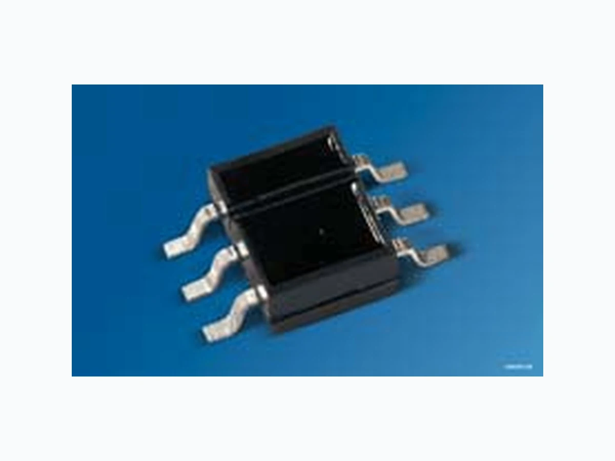
Reflective Interrupter with Schmitt-Trigger Reflexlichtschranke mit Schmitt-Trigger Version 1.1 SFH 9245
Ordering Information
Features: Besondere Merkmale:
- 940nm emitter in combination with a Schmitt-Trigger IC
- 940nm Emitter in Kombination mit einem Schmitt-Trigger IC
- Output: active "low" • Ausgang: aktiv "low"
- Daylight cut-off filter • Tageslichtsperrfilter
- Threshold current: typ. 1 mA • Einschaltstrom: typ. 1 mA
- Emitter and detector electrically isolated • Sender und Empfänger galvanisch getrennt
- Preconditioning acc. to JEDEC Level 4 • Vorbehandlung nach JEDEC Level 4 Applications Anwendungen
- Optical threshold switch • Optischer Schalter
- Pulse former • Pulsformer
- C o u n t e r •Z ä h l e r Type: Threshold current Ordering Code Typ: Schaltschwelle Bestellnummer Kodak neutral white testcard with 90% reflection; VCC = 5 V, d = 1 mm IF,on [mA] SFH 9245 1 ( ̞ 5) Q65111A3174
Version 1.1 SFH 9245 Maximum Ratings (TA = 25 °C) Grenzwerte Parameter Symbol Values Unit Bezeichnung Symbol Werte Einheit Emitter Sender Reverse voltage Sperrspannung VR 5V Forward current Durchlassstrom IF 50 mA Surge current Stoßstrom (tp ̞ 10 ǹs, D=0) IFSM 0.7 A Total power dissipation Verlustleistung Ptot 100 mW Thermal resistance junction - ambient 1) page 13 Wärmewiderstand Sperrschicht - Umgebung 1) Seite 13 RthJA 495 K / W Detector Empfänger Supply voltage Betriebsspannung VCC -0.5 ... 20 V Output voltage Ausgangsspannung VOUT -0.5 ... 20 V Output current Ausgangsstrom IOUT 50 mA Total power dissipation Verlustleistung Ptot 175 mW Interrupter Lichtschranke Operating and storage temperature range Betriebs- und Lagertemperatur Top; Tstg -40 ... 100 °C Total power dissipation Verlustleistung Ptot 150 mW
Version 1.1 SFH 9245 2013-11-05 3 Characteristics (TA = 25 °C) Kennwerte Parameter Symbol Values Unit Bezeichnung Symbol Werte Einheit Emitter Sender Emission wavelength Zentrale Emissionswellenlänge (typ) Ǹpeak 950 nm Forward voltage Durchlassspannung (IF = 50 mA, tp = 20 ms) (typ (max)) V F 1.45 (̞ 1.8) V Reverse current Sperrstrom (VR = 5 V) (typ (max)) I R not designed for reverse operation μA Temperature coefficient of Ie or Ǡe Temperaturkoeffizient von Ie bzw. Ǡe (typ) TC I -0.5 % / K Detector Empfänger Current consumption Stromaufnahme (VCC = 5 V) (typ (max)) I cc 3.3 (< 5) mA Current Consumption Stromaufnahme (VCC = 18 V) (typ) I cc 5m A Output voltage “high” Ausgangsspannung „high“ (IOUT = 0 mA) (typ (min)) V OH VCC (> 4.0) V Output voltage "low" Ausgangsspannung "low" (IOUT = 16 mA) (typ (max)) V OUT low 0.15 (< 0.4) V Rise time Anstiegzeit CC = 5 V, IF = 20 mA, RL = 280 kǣ) (typ) t r 0.02 μs Fall time Abfallzeit (VCC = 5 V, IF = 20 mA, RL = 280 kǣ) (typ) t f 0.01 μs
Version 1.1 SFH 9245 Operating Conditions Betriebsbedingungen Turn-on time Einschaltzeit CC = 5 V, IF = 20 mA, RL = 280 kǣ) (typ) t on 1 μs Turn-off time Ausschaltzeit (VCC = 5 V, IF = 20 mA, RL = 280 kǣ) (typ) t off 2 μs Interrupter Lichtschranke Threshold current Schaltschwelle (Kodak neutral white testcard with 90% reflection; V CC = 5 V, d = 1 mm) (typ (max)) I F,on 1 (̞ 5) mA Hysteresis Hysterese (typ (min..max) I Parameter Symbol Values Unit Bezeichnung Symbol Werte Einheit Supply voltage Betriebsspannung VCC 4 ... 18 V Output current Ausgangsstrom IOUT 16 mA Note: A bypass capacitor, 0.1 μF typical, connected between VCC and GND is recommended in order to stabilize power supply line. Anm.: Zur Stabilisierung der Versorgung wird ein Stützkondensator (angeschlossen zwischen V CC und GND) von typ. 0.1 μF empfohlen. Parameter Symbol Values Unit Bezeichnung Symbol Werte Einheit
Version 1.1 SFH 9245 2013-11-05 5 Mechanical test setup Mechanischer Testaufbau Block Diagram Blockschaltbild OHM02257 d Reflector with 90% reflexion (Kodak neutral white test card) OHF03865 Regulator Voltage GND OUT CCV Ω10 k
Version 1.1 SFH 9245 Test Circuit for Switching and Response Time Testschaltkreis für Schalt- und Reaktionszeit Switching Time Definitions Schaltzeitdefinitionen OHF00520 CCV OUT GND R = 47 Ω Input LR = 280 Ω μFC = 0.1 CCV OUT GND = 5 V OHF03866 PHLt tPLH 50% tf tr 50% 90% 10% Input Output
Version 1.1 SFH 9245 2013-11-05 7 Threshold Current vs. Distance 2) page 13 Schwellstrom vs. Entfernung 2) Seite 13 IF = f(d), TA = 25°C Relative Threshold 2) page 13 Relative Schwelle 2) Seite 13 Ee,on / Ee,on Vcc=5V = f(VCC), TA = 25°C Current Consumption 2) page 13 Stromaufnahme 2) Seite 13 ICC = f(VCC), TA = 25°C Output Voltage 2) page 13 Ausgangsspannung 2) Seite 13 VOL = f(IOUT, VCC), TA = 25°C OHF05613 FI d 1 2 3 456 7 mm 10 mA F, ONI F, OFFI OHF00507 0.5 0 5 10 15 20 0.6 0.7 0.8 0.9 1.1 1.2 1.3 1.5 V E VCC e, ON E e, ON_5 V OHF00510 0 0 5 10 15 20 V mA CCI VCC OHF00512 0 01 0 20 30 40 50mA 5 V OUTI 0.5 1.5 2.5 3.5 OLV V 10 V 15 V 20 V
Version 1.1 SFH 9245 Current Consumption vs. Ambient Temperature 2) page 13 Stromaufnahme vs. Umgebungstemperatur 2) Seite 13 ICC = f(TA, VCC) Forward Current 2) page 13 Durchlassstrom 2) Seite 13 IF = f(VF), single pulse, tp = 100 μs OHF00514 0-25 mA CCI AT 0 25 50 75 100˚C CCV = 5 V = 10 VCCV = 20 VVCC = 15 VVCC OHF03828 FI 10-4 0.5 1 1.5 2 2.5 V3 100 A FV -110 10-2
Version 1.1 SFH 9245 2013-11-05 9 Permissible Pulse Handling Capability Zulässige Pulsbelastbarkeit IF = f(tp), TA = 25 °C, duty cycle D = parameter Permissible Pulse Handling Capability Zulässige Pulsbelastbarkeit IF = f(tp), TA = 85 °C, duty cycle D = parameter Package Outline Maßzeichnung Dimensions in mm (inch). / Maße in mm (inch). 210-1-2-3-4-5 1010 1010 10 tp 10 10 s10 T tAIF D = IP T F Pt OHF05615 0.5 0.01 0.05 0.1 0.2 0.02 0.005 D = 0.05 0.10 0.15 0.20 0.25 0.30 0.35 0.40 0.45 0.50 0.55 0.60 0.75 210-1-2-3-4-5 1010 1010 10 tp 10 10 s10 T tAIF D = IP T F Pt OHF05616 0.5 0.01 0.05 0.1 0.2 0.02 0.005 D = 0.05 0.10 0.15 0.20 0.25 0.30 0.35 0.40 0.45 0.50 0.55 0.60 0.75
Version 1.1 SFH 9245 Pinning Anschlussbelegung Pin Description Anschluss Beschreibung 1A n o d e 2O U T CC 4 - (connect to GND or leave open) 5G N D 6C a t h o d e Recommended Solder Pad Empfohlenes Lötpaddesign
Version 1.1 SFH 9245 2013-11-05 11 Reflow Soldering Profile Reflow-Lötprofil Preconditioning: JEDEC Level 4 acc. to JEDEC J-STD-020D.01 00 s OHA04525 100 150 200 250 300 50 100 150 200 250 300 t T St t Pt Tp240 ˚C 217 ˚C 245 ˚C 25 ˚C L OHA04612 Profile Feature Profil-Charakteristik Ramp-up rate to preheat*) 25 °C to 150 °C 2 3 K/s Time tS TSmin to TSmax tS tL tP TL TP 100 12060 10 20 30 80 100 217 245 260 Time 25 °C to TP Time within 5 °C of the specified peak temperature TP - 5 K Ramp-down rate* TP to 100 °C All temperatures refer to the center of the package, measured on the top of the component * slope calculation DT/Dt: Dt max. 5 s; fulfillment for the whole T-range Ramp-up rate to peak*) TSmax to TP Liquidus temperature Peak temperature Time above liquidus temperature Symbol Symbol Unit Einheit Pb-Free (SnAgCu) Assembly Minimum MaximumRecommendation K/s K/s s s s s 480
Version 1.1 SFH 9245 Disclaimer Disclaimer Attention please! The information describes the type of component and shall not be considered as assured characteristics. Terms of delivery and rights to change design reserved. Due to technical requirements components may contain dangerous substances. For information on the types in question please contact our Sales Organization. If printed or downloaded, please find the latest version in the Internet. Packing Please use the recycling operators known to you. We can also help you – get in touch with your nearest sales office. By agreement we will take packing material back, if it is sorted. You must bear the costs of transport. For packing material that is returned to us unsorted or which we are not obliged to accept, we shall have to invoice you for any costs incurred. Components used in life-support devices or systems must be expressly authorized for such purpose! Critical components* may only be used in life-support devices** or systems with the express written approval of OSRAM OS. *) A critical component is a component used in a life-support device or system whose failure can reasonably be expected to cause the failure of that life-support device or system, or to affect its safety or the effectiveness of that device or system. **) Life support devices or systems are intended (a) to be implanted in the human body, or (b) to support and/or maintain and sustain human life. If they fail, it is reasonable to assume that the health and the life of the user may be endangered. Bitte beachten! Lieferbedingungen und Änderungen im Design vorbehalten. Aufgrund technischer Anforderungen können die Bauteile Gefahrstoffe enthalten. Für weitere Informationen zu gewünschten Bauteilen, wenden Sie sich bitte an unseren Vertrieb. Falls Sie dieses Datenblatt ausgedruckt oder heruntergeladen haben, finden Sie die aktuellste Version im Internet. Verpackung Benutzen Sie bitte die Ihnen bekannten Recyclingwege. Wenn diese nicht bekannt sein sollten, wenden Sie sich bitte an das nächstgelegene Vertriebsbüro. Wir nehmen das Verpackungsmaterial zurück, falls dies vereinbart wurde und das Material sortiert ist. Sie tragen die Transportkosten. Für Verpackungsmaterial, das unsortiert an uns zurückgeschickt wird oder das wir nicht annehmen müssen, stellen wir Ihnen die anfallenden Kosten in Rechnung. Bauteile, die in lebenserhaltenden Apparaten und Systemen eingesetzt werden, müssen für diese Zwecke ausdrücklich zugelassen sein! Kritische Bauteile* dürfen in lebenserhaltenden Apparaten und Systemen** nur dann eingesetzt werden, wenn ein schriftliches Einverständnis von OSRAM OS vorliegt. *) Ein kritisches Bauteil ist ein Bauteil, das in lebenserhaltenden Apparaten oder Systemen eingesetzt wird und dessen Defekt voraussichtlich zu einer Fehlfunktion dieses lebenserhaltenden Apparates oder Systems führen wird oder die Sicherheit oder Effektivität dieses Apparates oder Systems beeinträchtigt. **) Lebenserhaltende Apparate oder Systeme sind für (a) die Implantierung in den menschlichen Körper oder (b) für die Lebenserhaltung bestimmt. Falls Sie versagen, kann davon ausgegangen werden, dass die Gesundheit und das Leben des Patienten in Gefahr ist.
Version 1.1 SFH 9245 2013-11-05 13 Glossary Glossar 1) Thermal resistance: Mounting on PC-board with > 5 mm2 pad size 1) Wärmewiderstand: Montage auf PC-Board mit > 5 mm2 Padgröße 2) Typical Values: Due to the special conditions of the manufacturing processes of LED, the typical data or calculated correlations of technical parameters can only reflect statistical figures. These do not necessarily correspond to the actual parameters of each single product, which could differ from the typical data and calculated correlations or the typical characteristic line. If requested, e.g. because of technical improvements, these typ. data will be changed without any further notice. 2) Typische Werte: Wegen der besonderen Prozessbedingungen bei der Herstellung von LED können typische oder abgeleitete technische Parameter nur aufgrund statistischer Werte wiedergegeben werden. Diese stimmen nicht notwendigerweise mit den Werten jedes einzelnen Produktes überein, dessen Werte sich von typischen und abgeleiteten Werten oder typischen Kennlinien unterscheiden können. Falls erforderlich, z.B. aufgrund technischer Verbesserungen, werden diese typischen Werte ohne weitere Ankündigung geändert.
Version 1.1 SFH 9245 2013-11-05 14 Published by OSRAM Opto Semiconductors GmbH Leibnizstraße 4, D-93055 Regensburg www.osram-os.com © All Rights Reserved.