
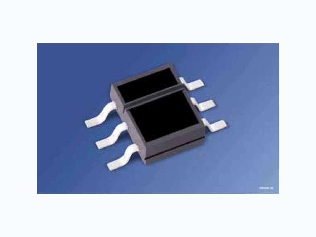
SFH9240 OSRAM
Document overview
- Manufacturer or author: Provided By www.digicamel.com(FREE DATASHEET DOWNLOAD SITE)
- PDF pages: 11
Technical content
Features
IR-GaAs-emitter in combination with a Schmitt-Trigger IC S F H 9240: Output active low Daylight cut-off filter Threshold current: typ. 3 mA Emitter and detector electrically isolated Preconditioning acc. to JEDEC Level 4
Applications
Optical threshold switch P u l s e f o r m e r Counter
Grenzwerte (TA = 25 °C) Maximum Ratings Bezeichnung Parameter Symbol Symbol Wert Value Einheit Unit Sender (GaAs-Diode) Emitter (GaAs diode) Sperrspannung Reverse voltage VR 5 V Vorwärtsgleichstrom Forward current IF 50 mA Stoßstrom (tP ≤ 10 μs) Surge current (tP ≤ 10 μs) IFSM 1.5 A Verlustleistung Power dissipation Ptot 80 mW Empfänger (Schmitt-Trigger IC) Detector (Schmitt-Trigger IC) Versorgungsspannung Supply voltage VCC – 0.5 … + 20 V Ausgangsspannung Output voltage VO – 0.5 … + 20 V Ausgangsstrom Output current (TA = 25 °C) IO 50 mA Verlustleistung Power dissipation Ptot 175 mW Reflexlichtschranke Light Reflection Switch Betriebs- und Lagertemperatur Operating and storage temperature range Top, Tstg – 40 … + 100 °C Verlustleistung Power dissipation Ptot 150 mW
Kennwerte (TA = 25 °C) Characteristics Bezeichnung Parameter Symbol Symbol Wert Value Einheit Unit Sender (GaAs-Diode) Emitter (GaAs diode) Durchlassspannung Forward voltage IF = 50 mA VF 1.25 (≤ 1.65) V Sperrstrom Reverse current VR = 5 V IR 0.01 (≤ 1) μA Kapazität Capacitance VR = 0 V, f = 1 MHz CO 25 pF Wärmewiderstand (Montage auf PC-Board mit > 5 mm2 Padgröße) Thermal resistance (mounting on pcb with > 5 mm2 pad size) RthJA 270 K/W Empfänger (Schmitt-Trigger IC) (wenn nicht anders angegeben, VCC = 5 V) Detector (Schmitt-Trigger IC) (unless otherwise specified, VCC = 5 V) Ausgangsspannung „high“ Output voltage “high” IO = 0 VOH VCC (> 4.0) V Ausgangsspannung „low“ Output voltage “low” IO = 16 mA VOL 0.15 (< 0.4) V Stromaufnahme Supply current VCC = 5 V VCC = 18 V ICC 3.3 (< 5) 5.0 mA Anstiegszeit 10% bis 90% Rise time 10% to 90% RL = 280 Ω, IF = 20 mA tr 20 ns Abfallzeit 90% bis 10% Fall time 90% to 10% RL = 280 Ω, IF = 20 mA tf 10 ns
Zur Stabilisierung der Versorgung wird ein Stützkondensator (angeschlossen zwischen VCC und GND) von typ. 0.1 μF empfohlen. A bypass capacitor, 0.1 μF typical, connected between VCC and GND is recommended in order to stabilize power supply line. Ausgangsverzögerungszeit Propagation delay time ”ON” RL = 280 Ω, IF = 20 mA tON 1 μs Ausgangsverzögerungszeit Propagation delay time “OFF” RL = 280 Ω, IF = 20 mA tOFF 2 μs Reflexlichtschranke Light Reflection Switch Schaltschwelle Threshold current, Kodak neutral white test card with 90% reflection VCC = 5 V, d = 1 mm IF, ON 3 (< 10) mA Hysterese Hysteresis IF, OFF / IF, ON 0.6 (0.5 … 0.9) Zulässiger Arbeitsbereich Operating Conditions Bezeichnung Parameter Symbol Symbol Wert Value Einheit Unit Versorgungsspannung Supply voltage VCC 4 … 18 V Ausgangsstrom Output current IO < 16 mA Kennwerte (TA = 25 °C) Characteristics (cont’d) Bezeichnung Parameter Symbol Symbol Wert Value Einheit Unit OHM02257 d Reflector with 90% reflexion (Kodak neutral white test card)
Threshold Current vs. Distance IF = f (d) Output Voltage VOL = f (IOUT, VCC) Perm. Pulse Handling Capability IF = f (tp), Duty cycle D = parameter, TA = 25 °C d OHF00684 FΙ mA 1234567 mm 9 F, ONΙ (SFH 9240 H L; SFH 9241 L H) H; SFH 9241 HF, OFFΙ (SFH 9240 L L) OHF00512 0 01 0 20 30 40 50mA 5 V OUTI 0.5 1.5 2.5 3.5 OLV V 10 V 15 V 20 V 1010 -2-3-4-5 1010 10 FI Pt =D T 210-1 10 tp 10 s 10 OHF02623 T tP IF 110 102 103 104 mA 0.005 0.05 0.1 0.02 0.01 D = 0.2 0.5 Relative Threshold Ee, ON/Ee, ON VCC = 5 V = f (VCC) Supply Current vs. Ambient Temperature ICC = f (TA, VCC) Perm. Pulse Handling Capability IF = f (tp), Duty cycle D = parameter, TA = 85 °C OHF00507 0.5 0 5 10 15 20 0.6 0.7 0.8 0.9 1.1 1.2 1.3 1.5 V E VCC e, ON Ee, ON_5 V OHF00514 0-25 mA CCI AT 0 25 50 75 100˚C CCV = 5 V = 10 VCCV = 20 VVCC = 15 VVCC 1010 -2-3-4-5 1010 10 FI Pt =D T 210-1 10 tp 10 s 10 OHF02622 T tP IF 110 102 103 104 mA 0.5 0.2 0.005 0.05 0.1 0.01 0.02 D = Supply Current ICC = f (VCC) OHF00510 0 0 5 10 15 20 V mA CCI VCC
Maßzeichnung Package Outlines Maße in mm (inch) / Dimensions in mm (inch). 3.4 (0.134) 3.0 (0.118) 5.8 (0.228) 6.2 (0.244) 0.15 (0.006) 0.13 (0.005) 2.1 (0.083) 1.7 (0.067) GPLY0504 4.2 (0.165) 3.8 (0.150) 0.3 (0.012) 0.5 (0.020) Raster (spacing) Raster (spacing) (0.1 (0.004) typ.) B A
0.2 M A
0.1 M B
2.54 (0.100) 1.27 (0.050) (5˚) (1.2 (0.047) typ.) (0.4 (0.016) typ.) Empfänger/Receiver Chip Positionen Type 1 2 3 4 5 6 SFH 9240 Anode OUT Vcc - GND Cathode
Empfohlenes Lötpaddesign Reflow Löten Recommended Solder Pad Reflow Soldering Maße in mm (inch) / Dimensions in mm (inch). Solder resist Lötstopplack Cu-area >5 mm Cu-Fläche >5 mm2 OHPY0030 3.9 (0.154) 1.2 (0.047) 1.27 (0.050) 0.6 (0.024) 1.27 (0.050) Paddesign Wärmeableitung for improved für verbesserte Padgeometrie Heat dissipation
Lötbedingungen Vorbehandlung nach JEDEC Level 4 Soldering Conditions Preconditioning acc. to JEDEC Level 4 Reflow Lötprofil für bleifreies Löten (nach J-STD-020C) Reflow Soldering Profile for lead free soldering (acc. to J-STD-020C) Lötbedingungen Soldering Conditions Bauform Type Drypack Level acc. to JEDEC A112-A Tauch-, Schwalllötung Dip, Wave Soldering Reflowlötung Reflow Soldering Kolbenlötung Iron Soldering Peak Temp. (solderbath) Max. Time in Peak Zone Peak Temp. (package temp.) Max. Time in Peak Zone (Iron temp.) OHLA0687 T t s 120 s max 100 150 200 250 300 Ramp Up 100 s max 50 100 150 200 250 300 Ramp Down
6 K/s (max)
3 K/s (max)
25 ˚C 30 s max 260 ˚C+0 ˚C -5 ˚C 245 ˚C±5 ˚C 240 ˚C 255 ˚C 217 ˚C Maximum Solder Profile Recommended Solder Profile 235 ˚C-0 ˚C +5 ˚C Minimum Solder Profile 10 s min
Gurtung / Polarität und Lage siehe Dokument: Short Form Katalog: Gurtung und Verpackung - SMT-Bauelemente - Gehäuse:SMT RLS Methode of Taping / Polarity and Orientation see document: Short Form Catalog: Tape and Reel - SMT-Components - Package: SMT-RLS Published by OSRAM Opto Semiconductors GmbH Leibnizstrasse 4, D-93055 Regensburg www.osram-os.com © All Rights Reserved. The information describes the type of component and shall not be considered as assured characteristics. Terms of delivery and rights to change design reserv ed. Due to technical requirements components may contain dangerous substances. For information on the types in question please contact our Sales Organization. Packing Please use the recycling operators known to you. We can also help you – get in touch with your nearest sales office. By agreement we will take packing material back, if it is sorted. You must bear the costs of tr ansport. For packing material that is returned to us unsorted or which we are not obliged to accept, we shall have to invoice you for any costs incurred. Components used in life-support devices or system s must be expressly authorized for such purpose! Critical components 1 , may only be used in life-support devices or systems 2 with the express written approval of OSRAM OS. 1 A critical component is a component usedin a life-support device or system whose failure can reasonably be expected to cause the failure of that life-support device or system, or to affect its safety or effectiveness of that device or system. 2 Life support devices or systems are intended (a) to be implanted in the human body, or (b) to support and/or maintain and sustain human life. If they fail, it is reasonable to assume that the health of the user may be endangered
Click to View Pricing, Inventory, Delivery & Lifecycle Information: Osram Opto Semiconductor: SFH 9240-Z