
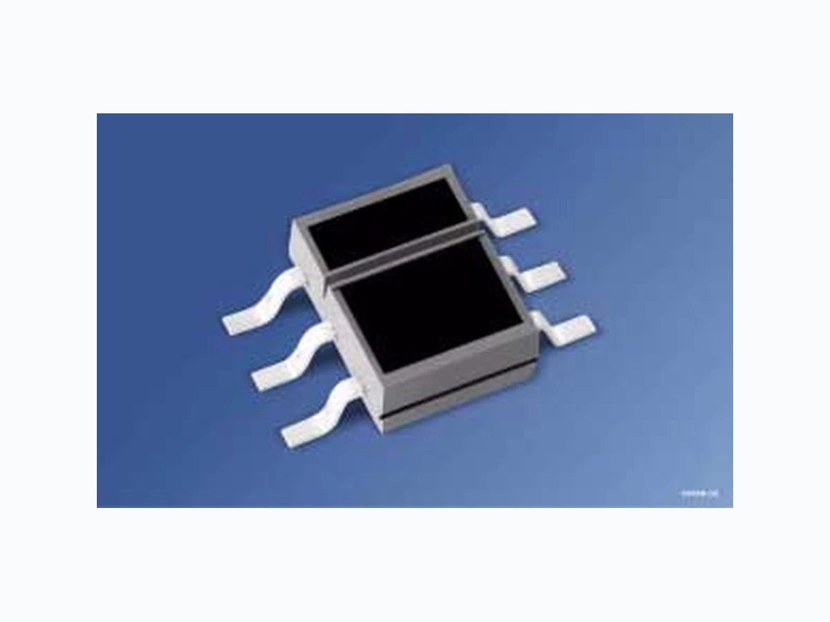
SFH9210 OSRAM
Document overview
- Manufacturer or author: Provided By www.digicamel.com(FREE DATASHEET DOWNLOAD SITE)
- PDF pages: 10
Technical content
Features
Long operating distance (2-10mm) IR-GaAs-VCSEL (Vertical Cavity Surface Emitting Laser) in combination with a Silicon NPN phototransistor Narrow beam characteristics of the emitter Daylight cut-off filter
Applications
Position sensor End position switch Speed monitoring and regulating Motion sensor
Sender (GaAs-VCSEL-Diode) Emitter (GaAs VCSEL diode) Sperrspannung Reverse voltage VR 3V Vorwärtsgleichstrom Forward current IF 10 mA Verlustleistung Power dissipation Ptot 25 mW Empfänger (Si-Fototransistor) Detector (silicon phototransistor) Dauer-Kollektor-Emitter-Sperrspannung Continuous collector-emitter voltage VCE 16 V Kollektor-Emitter-Sperrspannung, (t ≤ 2 min) Collector-emitter voltage, (t ≤ 2 min) VCE 30 Emitter-Kollektor-Sperrspannung Emitter-collector voltage VEC 7 Kollektorstrom Collector current IC 20 mA Verlustleistung Total power dissipation Ptot 100 mW Reflexlichtschranke Reflective Interrupter Lagertemperatur Storage temperature range Tstg - 40 … + 85 °C Betriebstemperatur Operating temperature range TOP - 40 … + 85 Elektrostatische Entladung Electrostatic discharge ESD 400 V Umweltbedingungen / Environment conditions 3 K3 acc. to EN 60721-3-3 (IEC 721-3-3)
Kennwerte (TA = 25 °C) Characteristics Bezeichnung Parameter Symbol Symbol Wert Value Einheit Unit Sender (GaAs-VCSEL-Diode) Emitter (GaAs-VCSEL diode) Wellenlänge der Strahlung Wavelength at peak emission IF = 8 mA, tp = 20 ms λpeak 850 nm Spektrale Bandbreite bei 50% von Imax Spectral bandwidth at 50% of Imax IF = 8 mA ∆λ 1n m Schwellenstrom1) Threshold current1) Ith 2.6 (<5) mA Durchlaβspannung Forward voltage IF = 10 mA VF 1.8 (≤ 2.3) V Sperrstrom Reverse current VR = 3 V IR 0.01 (≤ 1) µA Kapazität Capacitance VR = 0 V, f = 1 MHz CO 25 pF Wärmewiderstand2) Thermal resistance2) RthJA 1200 K/W Empfänger (Si-Fototransistor) Detector (silicon phototransistor) Kapazität Capacitance VCE = 5 V, f = 1 MHz CCE 10 pF Kollektor-Emitter-Reststrom Collector-emitter leakage current VCE = 20 V ICEO 3 (≤ 200) nA Fotostrom (Fremdlichtempfindlichkeit) Photocurrent (outside light density) VCE = 5 V, EV = 1000 Lx IP 3.5 mA Wärmewiderstand2) Thermal resistance2) RthJA 270 K/W
Kodak neutral white test card, 90% Reflexion IF = 8 mA; VCE = 5 V; d = 5 mm (see note on page 5) ICE 1 ... 8 1 ... 2 2.5 ... 5 4 ... 8 mA Kollektor-Emitter-Sättigungsspannung Collector-emitter-saturation voltage Kodak neutral white test card, 90% Reflexion IF = 8 mA; d = 5 mm; IC = 0.3 x ICE min. (see note on page 5) VCE sat 0.15 (≤ 0.6) V 1) Der VCSEL emittiert nur bei Flussströmen größer als Ith VCSEL only emits at forward currents higher than Ith 2) Montage auf PC-Board mit > 5 mm2 Padgröβe Mounting on pcb with > 5 mm2 pad size 3) Nur eine Gruppe innerhalb einer Verpackungseinheit. Bezug von Einzelgruppen ist nicht möglich. Only single group within one packing unit. Single bins can not be ordered. Kennwerte (TA = 25 °C) Characteristics (cont’d) Bezeichnung Parameter Symbol Symbol Wert Value Einheit Unit OHM02257 d Reflector with 90% reflexion (Kodak neutral white test card)
Schaltzeiten (TA = 25 °C, VCC = 5 V, IC = 1 mA1), RL = 1 kΩ) Switching Times Bezeichnung Parameter Symbol Symbol Wert Value Einheit Unit Einschaltzeit Turn-on time tein ton 65 µs Anstiegzeit Rise time tr 50 µs Ausschaltzeit Turn-off time taus toff 55 µs Abfallzeit Fall time tf 50 µs 1) IC eingestellt über den Durchlassstrom der Sendediode, de n Reflexionsgrad und den Abstand des Reflektors vom Bauteil (d) IC as a function of the forward curren t of the emitting diode, the degree of reflection and the distance between reflector and component (d) Anm.:- Es wird empfohlen die Lichtschranke bei dem spez ifizierten Arbeitpunkt von ca. 8mA für den Emitter einzusetzten, weil andere Betriebs ströme zu einem größeren Streubereich beim Koppelfaktor führen. Der Abgleich erfolgt über den Arbeitswiderstand am Detektor. Von einem Einsatz der Lichtschranke mit glänzenden oder gar spiegelnden Oberflächen wird abgeraten. Die Abstrahlcharakteristik de s Senders ändert sich sowohl über die Temperatur als auch mit dem Flußstrom stärker als bei Standardemittern und führt somit ebenfalls zur Erhöhung des Streubereichs beim Koppelfaktor. Bei diffuser Streuung ist dieser Einfluß jedoch gering, und kann für die meisten Anwendungen vernachlässigt werden. Note: It is recomended to use the interrupter at the specifie d emitter current of about 8mA, as other operating currents lead to a larger coupling factor variation. The tuning is done using the operating resistor on the detector side. It is not recomended to use the interrupter in combi nation with shiny or mirror like surfaces. Changes in temperatures and operating current are having a bigger influence on the radiation characteristic as it is the case for standard emitters. This means a higher variance of the coupling factor. For diffuse surfaces the mentioned influence is low, and can be neglected for most of the applications. OHM02258 Ι F VCC R L Ι C Output
Kodak 90% Max. Permissible Forward Current IF = f (TA) Radiation characteristics Ιrel = f (ϕ) IC ICmax 0.0 0.2 0.4 0.6 0.8 1.0 1.2 0 5 10 15 20 I C;rel mm d 1.0 0.6 0.8 0.2 0.4 100˚ 80˚ 90˚ 0.81.0 0.6 0.4 60˚ 70˚ 50˚ 40˚ 30˚ 20˚ ϕ 10˚ OHF00144 Switching Characteristics t = f (RL) TA = 25 °C, IF = 8 mA Forward Current IF = f (VF) IF =10mA OHO00785 t LR 10 1 10 -1 10 2 10 3 s 10 0 10 1kΩ µ Ι C 100 µA t on = 1 mACΙ t off t on t off OHF00143 IF FV 10-3 -210 -110 100 101 102 mA 0.5 1 1.5 2 2.5V Transistor Capacitance (typ.) CCE = f (VCE), TA = 25 °C, f = 1 MHz Threshold Current Ith = f (TΑ) Collector Current IC = f (IF), d = 5 mm, Kodak 90% OHO00374 C CE pF VCE -110 010 110 210V OHF00145 Ith AT 20 40 60 80 100˚C0 0.5 1.0 1.5 2.0 2.5 3.0 3.5 4.0 mA 0.0 0.2 0.4 0.6 0.8 1.0 1.2 05 1 0 I C;rel mA I F
Maßzeichnung Package Outlines Maße werden wie folgt angegeben: mm (inch) / Dimensions are specified as follows: mm (inch). 3.4 (0.134) 3.0 (0.118) 5.8 (0.228) 6.2 (0.244) 0.15 (0.006) 0.13 (0.005) 2.1 (0.083) 1.7 (0.067) GPLY0505 4.2 (0.165) 3.8 (0.150) 0.3 (0.012) 0.5 (0.020) Raster (spacing) Raster (spacing) (0.1 (0.004) typ.) B A
0.2 M A
0.1 M B
2.54 (0.100) 1.27 (0.050) (5˚) (1.2 (0.047) typ.) Empfänger/Receiver Chip Positionen Type 1 2 3 4 5 6 SFH 9210 Anode – Emitter Collector – Cathode
Empfohlenes Lötpaddesign IR-Reflow Löten Recommended Solder Pad IR Reflow Soldering Maße werden wie folgt angegeben: mm (inch) / Dimensions are specified as follows: mm (inch). Solder resist Lötstopplack Cu-area >5 mm Cu-Fläche >5 mm2 OHPY0030 3.9 (0.154) 1.2 (0.047) 1.27 (0.050) 0.6 (0.024) 1.27 (0.050) Paddesign Wärmeableitung for improved für verbesserte Padgeometrie Heat dissipation
Bitte Verarbeitungshinweise für SMT-Bauelemente beachten! Please observe the handling guidelines for SMT devices! IR-Reflow Lötprofil (nach IPC 9501) IR Reflow Soldering Profile (acc. to IPC 9501) Löthinweise Soldering Conditions Bauform Type Drypack Level acc. to IPS-stand. 020 Tauch-, Schwalllötung Dip, Wave Soldering Reflowlötung Reflow Soldering Kolbenlötung Iron Soldering Peak Temp. (solderbath) Max. Time in Peak Zone Peak Temp. (package temp.) Max. Time in Peak Zone (Iron temp.) OHLY0597 50 100 150 200 2 100 150 200 250 300 T t C s 240-245 C 10-40 s 183 C 120 to 180 s defined for Preconditioning: up to 6 K/s ramp-down rate up to 6 K/s ramp-up rate up to 6 K/s defined for Preconditioning: 2-3 K/s
Gurtung / Polarität und Lage siehe Dokument: Short Form Katalog: Gurtung und Verpackung - SMT-Bauelemente - Gehäuse:SMT RLS Methode of Taping / Polarity and Orientation see document: Short Form Catalog: Tape and Reel - SMT-Components - Package: SMT-RLS Published by OSRAM Opto Semiconductors GmbH Wernerwerkstrasse 2, D-93049 Regensburg www.osram-os.com © All Rights Reserved. The information describes the type of component and shall not be considered as assured characteristics. Terms of delivery and rights to change design reserv ed. Due to technical requirements components may contain dangerous substances. For information on the types in question please contact our Sales Organization. Packing Please use the recycling operators known to you. We can also help you – get in touch with your nearest sales office. By agreement we will take packing material back, if it is sorted. Y ou must bear the costs of transport. For packing material that is returned to us unsorted or which we are not obliged to accept, we shall have to invoice you for any costs incurred. Components used in life-support devices or system s must be expressly authorized for such purpose! Critical components 1 may only be used in life-support devices or systems 2 with the express written approval of OSRAM OS. 1 A critical component is a component used in a life-support device or system whose failure can reasonably be expected to cause the failure of that life-support device or system, or to affect its safety or effectiveness of that device or system. 2 Life support devices or systems are intended (a) to be implanted in the human body, or (b) to support and/or maintain and sustain human life. If they fail, it is reasonable to assume that the health of the user may be endangered.