
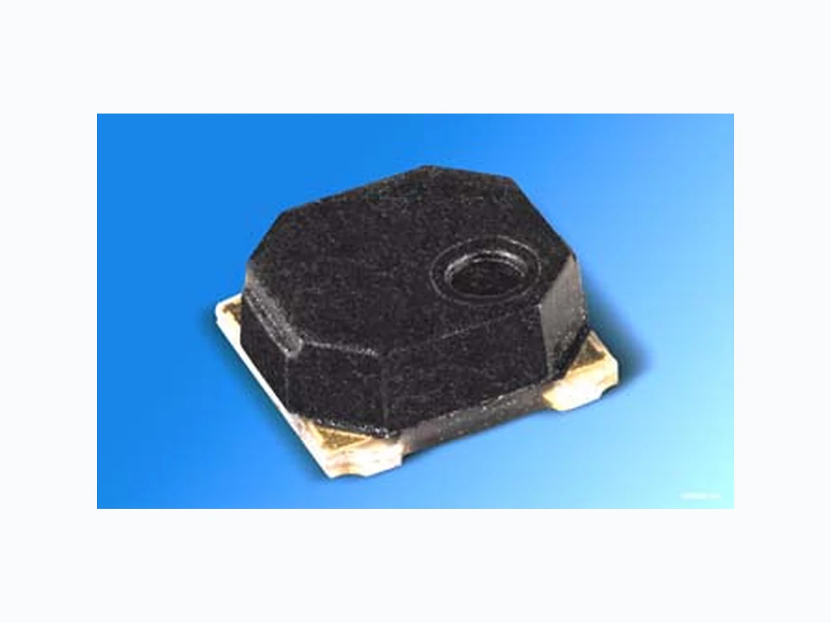
SFH7710 OSRAM
Document overview
- Manufacturer or author: Provided By www.digicamel.com(FREE DATASHEET DOWNLOAD SITE)
- PDF pages: 10
Technical content
Features
optical detection of orientationby gravity dependent position of a steel ball Low current consumption digital output, open drain defined range of switching angle very small SMD package IC controlled sensor
Applications
Digital cameras Camcorders Mobile phones Computer peripherals
Vcc -0.2...6 V Ausgangsspannung Output voltage Ausgangsstrom Output current Io 10 mA Lagertemperatur Storage temperature range Ts -40...100 °C Elektrostatische Entladung Electrostatic discharge - human body model (according to: Class I) - machine model (according to: AEC-Q100-003-REV-D, classification M3) V ESD 200 kV V latch up Schutz latch-up protection (according to: EIA/JESD78 Class I) 20 mA
- Der Emitter wird mit 10mA gepulst betrieben; das bedeutet, dass jeder Widerstand in Serie zu Vcc einen Spannungsabfall in der Versorgungsleitung verursacht. Daher wird empfohlen, diesen Serienwiderstand kleiner 10 Ohm zu halten. Die minimale Versorgungsspanung (Vcc min ) darf keinesfalls unterschritten werden. * The emitter is driven with 10 mA in pulsed m ode; this means that any series resistor to Vcc causes a voltage drop on the power line. It is recommended to keep the series resistor below 10 Ohm. The supply voltage may not fall below Vcc min Empfohlener Arbeitsbereich Recommended Operating conditions Bezeichnung Parameter Symbol Symbol Wert Value Einheit Unit Min Max Betriebstemperatur Full operational ambient temperature range ΤA -20 +65 °C Versorgungsspannung Supply voltage Vcc 2.3 3.6 V Versorgungsspannungsstörungen * (Frequenzbereich: 0...20kHz) Supply voltage noise (frequency range: 0...20kHz) dVcc pp 0.2 V Ausgangsspannung Output voltage Vo 1.7 3.6 V Pull-up Widerstand Pull-up resistance Rpull up 10 100 kOhm
(TA=25°C) Bezeichnung Parameter Symbol Symbol Wert Value Einheit Unit Min. Typ. Max. Minimale Betriebsspannung für Startphase(siehe Figure 3) Minimum required supply bvoltage for start-up (see Figure 3) Vcc,start 0.8 2.0 V Länge der Startphase (siehe Figure 3) Start up time (see Figure 3) tstart 60 120 ms Durchschnittlicher Stromaufnahme1) mean current consumption1) 1) gepulster Betrieb: Dauer LED an: ~44µs / Dauer LED aus: ~90ms pulsed operation mode: LED on time: ~44µs / LED off time: ~90ms Imean 50 µA Spitzenstromaufnahme2) peak current consumption1) 2) gepulster Betrieb: Dauer LED an: ~44µs / Dauer LED aus: ~90ms pulsed operation mode: LED on time: ~44µs / LED off time: ~90ms Ipeak 20 mA Ausgangsleckstrom „high“ Output leakage current „high“ VO = 3,6V IOH 5µ A Ausgangsleckstrom „low“ Output leakage current „low“ IOl = 10mA (Vcc = 2,3V) VOL 0.5 V Aktualisierung des Ausgangssignals 1) Refresh of output signal 1) trefresh 90 ms Kippwinkel mit Ausgangszustand „low“ (siehe Figure1) Tilt angle with output state „low“ (see Figure 1) αt 70 200 ° Kippwinkel mit Ausgangszustand „high“ (siehe Figure1) Tilt angle with output state „high“ (see Figure 1) αu 250 20 °
x y 70˚ 20˚ 200˚ 250˚ Switching Range Switching Range αβ z y 60˚-60˚ Sensing Range y x z βα outV = high = lowVout Funktionsdiagramm Functional diagram Figure1: Erfassungscharakteristik / Detecting characteristics (Unter extremen Bedingungen (hohe Temperatur und/oder hohe relative Feuchte) kann vorübergehend eine grössere Schaltwinkeltoleranz auftreten) (Under extreme conditions (high temperature and/or high relative humidity) a wider switching angle tolerance can occur temporarily)
Figure2: Blockdiagramm (empfohlener Pull-Up-Widerstand Rpull up = 10kOhm...100kOhm) Block diagram (recommended Pull up resistance Rpull up = 10kOhm...100kOhm) OHF03939 Photo- transistorLED LED Anode (must not be connected) CCV OV boundaries Device ASIC pull upR GND
Startverhalten und Ablaufdiagramm Start-up behavior and Timing diagramm Der Ausgang ist immer hochohmig, wenn an Vcc keine Spannung angeschlossen ist. Wenn die Versorgungsspannung Vcc , start erreicht, bleibt der Ausgang für 60ms <tstart <120ms auf „low“. Anschließend findet etwa alle 90ms eine Messung der Orientierung statt und der Ausgang wird entprechend geschalten. The Output is always high ohmic when voltage at V cc is not connected. When supply voltage reaches V cc, start the sensor output stays low for 60ms <tstart <120ms. Subsequently approx. every 90ms the orientation is measured and the output is set accordingly. Figure 3: Startverhalten und Ablaufdiagramm des Sensors Start-up behavior and Timing diagram of sensor OHF03938 CCVSupply Voltage VCC, min CC, startV peak LED Current ILED I startt OL OHV Output VoltageV VO Output Voltage αfor OLV VO OHV startt startt refresht trefresh trefresh startt t t t t
Maßzeichnung Package Outlines Maße in mm (inch) / Dimensions in mm (inch) Anschlußbelegung Pin configuration Pin # Description 1G N D 2V c c LED Anode (must not be connected) 4O u t GPLY7037 (2.3 (0.091)) 4.6 (0.181) 4.2 (0.165) (2.35 (0.093)) 4.7 (0.185) 4.4 (0.173) 4.6 (0.181) 4.2 (0.165) GPLY7039 R0.5 (0.020) Orientation mark GPLY7038 (0.4 (0.016)) (3.82 (0.150)) 2.0 (0.079) 1.6 (0.063) (4.1 (0.161))
Empfohlenes Lötpaddesign Recommended Solderpad Design Maße in mm (inch) / Dimensions in mm (inch) Gurtung und Lage Method of taping and orientation Maße in mm (inch) / Dimensions in mm (inch) OHPY3459 1.9 (0.075) 2.0 (0.079) 1.2 (0.047) 1.3 (0.051) OHA03983 1.5 +0.1 5.5 1.75 4.7 4.85 1.5 0.3 2.25 ±0.05
Lötbedingungen Vorbehandlung nach JEDEC Level 4 Soldering Conditions Preconditioning acc. to JEDEC Level 4 FFigure 8: Temperaturprofil für Reflow-Löten (Der Sensor darf nach dem Löten nicht gewaschen werden.) Temperature profile for Reflow-soldering (Do not wash the sensor after soldering) Published by OSRAM Opto Semiconductors GmbH Wernerwerkstrasse 2, D-93049 Regensburg www.osram-os.com © All Rights Reserved. The information describes the type of component and shall not be considered as assured characteristics. Terms of delivery and rights to change design reserv ed. Due to technical requirements components may contain dangerous substances. For information on the types in question please contact our Sales Organization. Packing Please use the recycling operators known to you. We can also help you – get in touch with your nearest sales office. By agreement we will take packing material back, if it is sorted. Y ou must bear the costs of transport. For packing material that is returned to us unsorted or which we are not obliged to accept, we shall have to invoice you for any costs incurred. Components used in life-support devices or system s must be expressly authorized for such purpose! Critical components 1 , may only be used in life-support devices or systems 2 with the express written approval of OSRAM OS. 1 A critical component is a component usedin a life-support device or system whose failure can reasonably be expected to cause the failure of that life-support device or system, or to affect its safety or effectiveness of that device or system. 2 Life support devices or systems are intended (a) to be implanted in the human body, or (b) to support and/or maintain and sustain human life. If they fail, it is reasonable to assume that the health of the user may be endangered. OHLA0687 T t s 120 s max 100 150 200 250 300 Ramp Up 100 s max 50 100 150 200 250 300 Ramp Down
6 K/s (max)
3 K/s (max)
25 ˚C 30 s max 260 ˚C+0 ˚C -5 ˚C 245 ˚C ±5 ˚C 240 ˚C 255 ˚C 217 ˚C Maximum Solder Profile Recommended Solder Profile 235 ˚C-0 ˚C +5 ˚C Minimum Solder Profile 10 s min