
SFH601_15 VISHAY
Document overview
- Manufacturer or author: Provided By www.digicamel.com(FREE DATASHEET DOWNLOAD SITE)
- PDF pages: 10
Technical content
www.vishay.com Vishay Semiconductors Rev. 1.6, 23-Jul-15 1 Document Number: 83663 For technical questions, contact: optocoupleranswers@vishay.com THIS DOCUMENT IS SUBJECT TO CHANGE WITHOUT NOTICE. THE PRODUCTS DESCRIBED HEREIN AND THIS DOCUMENT ARE SUBJECT TO SPECIFIC DISCLAIMERS, SET FORTH AT www.vishay.com/doc?91000 Optocoupler, Phototransistor Output, with Base Connection
DESCRIPTION
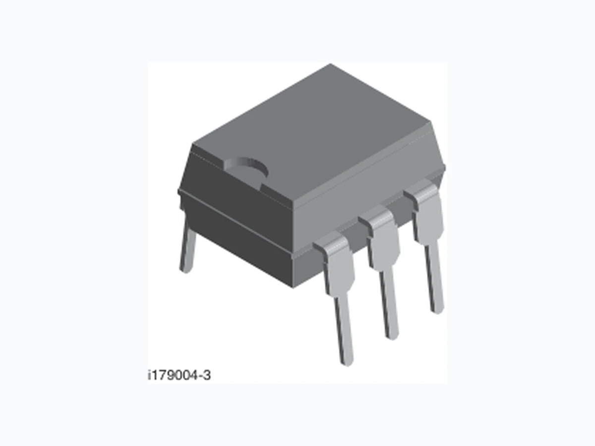
The SFH601 is an optocoupler with a gallium arsenide LED emitter which is optically coupled with a silicon planar phototransistor detector. The component is packaged in a plastic plug-in case 20 AB DIN 41866. The coupler transmits signals between two electrically isolated circuits.
FEATURES
- Isolation test voltage (1.0 s), 5300 VRMS
- V CEsat 0.25 ( 0.4) V, IF = 10 mA, IC = 2.5 mA
- Built to conform to VDE requirements
- Highest quality premium device
- Long term stability
- Storage temperature, -55 ° to +150 °C
- Material categorization: for definitions of compliance please see www.vishay.com/doc?99912 AGENCY APPROVALS
- UL1577, file no. E52744 system code H or J, double protection
- DIN EN 60747-5-5 (VDE 0884-5) available with option 1
- CSA 93751
- BSI IEC 60950; IEC 60065 Note
- For additional information on the availa ble options refer to option information. B C E A C NC i179004-11 i179004-3
ORDERING INFORMATION
SFH601-#X0## PART NUMBER CTR BIN PACKAGE OPTION AGENCY CERTIFIED/PACKAGE CTR (%) UL, BSI, CSA 40 to 80 63 to 125 100 to 200 160 to 320 DIP-6 SFH601-1 SFH601-2 SFH601-3 SFH601-4 DIP-6, 400 mil, option 6 SFH601-1X006 SFH601-2X006 SFH601-3X006 SFH601-4X006 SMD-6, option 7 SFH601-1X007 SFH601-2X007T SFH601-3X007(T) SFH601-4X007(T) SMD-6, option 9 SFH601-1X009T SFH601-2X009 SFH601-3X009 SFH601-4X009(T) VDE, cUL, UL, BSI 40 to 80 63 to 125 100 to 200 160 to 320 DIP-6, option 1 SFH601-1X001 SFH601-2X001 - SFH601-4X001 DIP-6, 400 mil, option 6 SFH601-1X016 - SFH601-3X016 SFH601-4X016 SMD-6, option 7 SFH601-1X017 SFH601-2X017(T) SFH601-3X017(T) - SMD-6, option 9 - - SFH601-3X019(T) - > 0.1 mm 10.16 mm > 0.7 mm 7.62 mm DIP Option 7 Option 6 Option 9
www.vishay.com Vishay Semiconductors Rev. 1.6, 23-Jul-15 2 Document Number: 83663 For technical questions, contact: optocoupleranswers@vishay.com THIS DOCUMENT IS SUBJECT TO CHANGE WITHOUT NOTICE. THE PRODUCTS DESCRIBED HEREIN AND THIS DOCUMENT ARE SUBJECT TO SPECIFIC DISCLAIMERS, SET FORTH AT www.vishay.com/doc?91000 Notes
- Stresses in excess of the absolu te maximum ratings can cause permanent damage to the device. Functional operation of the device is not implied at these or any other conditions in excess of those give n in the operational sections of this document. Exposure to abs olute maximum ratings for extended periods of the time can adversely affect reliability. (1) Refer to reflow profile for soldering conditions for surface mounted devices (SMD). Refer to wave profile for soldering conditions for through hole devices (DIP). Note
- Minimum and maximum values are testing requirements. Typical values are characteristics of the device and are the result of en gineering evaluation. Typical values are for information only and are not part of the testing requirements. ABSOLUTE MAXIMUM RATINGS (Tamb = 25 °C, unless otherwise specified) PARAMETER TEST CONDITION SYMBOL VALUE UNIT INPUT Reverse voltage V R 6V DC forward current IF 60 mA Surge forward current t = 10 μs I FSM 2.5 A Total power dissipation P diss 100 mW OUTPUT Collector emitter voltage V CEO 100 V Emitter base voltage VEBO 7V Collector current IC 50 mA t = 1.0 ms I C 100 mA Power dissipation Pdiss 150 mW COUPLER Storage temperature range T stg -55 to +150 °C Ambient temperature range T amb -55 to +100 °C Junction temperature Tj 100 °C Soldering temperature (1) Max. 10 s, dip soldering: distance to seating plane 1.5 mm Tsld 260 °C ELECTRICAL CHARACTERISTICS (Tamb = 25 °C, unless otherwise specified) PARAMETER TEST CONDITION PART SYMBOL MIN. TYP. MAX. UNIT INPUT Forward voltage I F = 60 mA V F - 1.25 1.65 V Breakdown voltage I R = 10 μA V BR 6--V Reverse current V R = 6 V I R -0 . 0 1 1 0μ A Capacitance V F = 0 V, f = 1 MHz C O -2 5-p F Thermal resistance R thja - 750 - K/W OUTPUT Collector emitter capacitance f = 1 MHz, V CE = 5 V C CE -6 . 8-p F Collector base capacitance f = 1 MHz, V CB = 5 V C CB -8 . 5-p F Emitter base capacitance f = 1 MHz, V EB = 5 V C EB -1 1-p F Thermal resistance R thja - 500 - K/W Collector emitter leakage current V CE =10 V SFH601-1 I CEO - 2 50 nA SFH601-2 I CEO - 2 50 nA SFH601-3 I CEO - 5 100 nA SFH601-4 I CEO - 5 100 nA COUPLER Saturation voltage collector emitter I F = 10 mA, IC = 2.5 mA V CEsat - 0.25 0.4 V Capacitance (input to output) V I-O = 0, f = 1 MHz C IO -0 . 6-p F
www.vishay.com Vishay Semiconductors Rev. 1.6, 23-Jul-15 3 Document Number: 83663 For technical questions, contact: optocoupleranswers@vishay.com THIS DOCUMENT IS SUBJECT TO CHANGE WITHOUT NOTICE. THE PRODUCTS DESCRIBED HEREIN AND THIS DOCUMENT ARE SUBJECT TO SPECIFIC DISCLAIMERS, SET FORTH AT www.vishay.com/doc?91000 Note
- Current transfer ratio and collector emitter leakage current by dash number. Fig. 1 - Linear Operation (without Saturation) Fig. 2 - Switching Operation (with Saturation) CURRENT TRANSFER RATIO PARAMETER TEST CONDITION PART SYMBOL MIN. TYP. MAX. UNIT IC/IF at VCE = 5.0 V IF = 10 mA SFH601-1 CTR 40 - 80 % SFH601-2 CTR 63 - 125 % SFH601-3 CTR 100 - 200 % SFH601-4 CTR 160 - 320 % I F = 1 mA SFH601-1 CTR 13 30 - % SFH601-2 CTR 22 45 - % SFH601-3 CTR 34 70 - % SFH601-4 CTR 56 90 - % SWITCHING CHARACTERISTICS PARAMETER TEST CONDITION PART SYMBOL MIN. TYP. MAX. UNIT NON-SATURATED Current V CC = 5 V, RL = 75 IF -1 0- m A Rise time V CC = 5 V, RL = 75 tr -2- μ s Fall time V CC = 5 V, RL = 75 tf -2- μ s Turn-on time V CC = 5 V, RL = 75 ton -3- μ s Turn-off time V CC = 5 V, RL = 75 toff -2 . 3- μ s SATURATED Current SFH601-1 I F -2 0- m A SFH601-2 I F -1 0- m A SFH601-3 I F -1 0- m A SFH601-4 I F -0 . 5-m A Rise time SFH601-1 t r -2- μ s SFH601-2 t r -3- μ s SFH601-3 t r -3- μ s SFH601-4 t r -4 . 6- μ s Fall time SFH601-1 t f -1 1-μ s SFH601-2 t f -1 4-μ s SFH601-3 t f -1 4-μ s SFH601-4 t f -1 5-μ s Turn-on time SFH601-1 t on -3- μ s SFH601-2 t on -4 . 2- μ s SFH601-3 t on -4 . 2- μ s SFH601-4 t on -6- μ s Turn-off time SFH601-1 t off -1 8-μ s SFH601-2 t off -2 3-μ s SFH601-3 t off -2 3-μ s SFH601-4 t off -2 5-μ s isfh601_01 RL =7 5 Ω VCC = 5 V IC 47 Ω IF IF 1k Ω VCC =5V 47 Ω isfh601_02
www.vishay.com Vishay Semiconductors Rev. 1.6, 23-Jul-15 4 Document Number: 83663 For technical questions, contact: optocoupleranswers@vishay.com THIS DOCUMENT IS SUBJECT TO CHANGE WITHOUT NOTICE. THE PRODUCTS DESCRIBED HEREIN AND THIS DOCUMENT ARE SUBJECT TO SPECIFIC DISCLAIMERS, SET FORTH AT www.vishay.com/doc?91000 Note the safety ratings shall be ensured by means of protective circuits. TYPICAL CHARACTERISTICS (Tamb = 25 °C, unless otherwise specified) Fig. 3 - Current Transfer Ratio vs. Diode Current Fig. 4 - Current Transfer Ratio vs. Diode Current SAFETY AND INSULATION RATINGS PARAMETER TEST CONDITION SYMBOL VALUE UNIT Climatic classification Accordin g to IEC 68 part 1 55 / 100 / 21 Comparative tracking index CTI 175 Maximum rated withstanding isolation voltage t = 1 min V ISO 4420 V RMS Maximum transient isolation voltage V IOTM 8000 V Maximum repetitive peak isolation voltage V IORM 890 V Isolation resistance VIO = 500 V, Tamb = 25 °C R IO 1012 VIO = 500 V, Tamb = 100 °C R IO 1011 Output safety power P SO 700 mW Input safety current ISI 400 mA Input safety temperature T SI 175 °C Creepage distance Standard DIP-4 7m m Clearance distance Standard DIP-4 7m m Creepage distance 400 mil DIP-4 8m m Clearance distance 400 mil DIP-4 8m m Insulation thickness DTI 0.4 mm (%) 103 102 100 10-1 101 210055 IF (mA)isfh601_03 (TA = - 25 ˚C, VCE = 5.0 V) IC/IF = f (IF) IC IF (%) 103 102 100 10-1 101 210055 IF (mA)isfh601_04 (TA = 0 °C, VCE = 5.0 V) IC/IF = f (IF) IC IF DC Pulsmode Pulse
www.vishay.com Vishay Semiconductors Rev. 1.6, 23-Jul-15 5 Document Number: 83663 For technical questions, contact: optocoupleranswers@vishay.com THIS DOCUMENT IS SUBJECT TO CHANGE WITHOUT NOTICE. THE PRODUCTS DESCRIBED HEREIN AND THIS DOCUMENT ARE SUBJECT TO SPECIFIC DISCLAIMERS, SET FORTH AT www.vishay.com/doc?91000 Fig. 5 - Current Transfer Ratio vs. Diode Current Fig. 6 - Current Transfer Ratio vs. Diode Current Fig. 7 - Current Transfer Ratio vs. Diode Current Fig. 8 - Current Transfer Ratio vs. Diode Current Fig. 9 - Transistor Characteristics Fig. 10 - Output Characteristics 103 102 100 10-1 101 210055 isfh601_05 VCE = 5.0 V) IC/IF = f (IF) DC Pulsbetrieb Pulse (%) IF (mA) IC IF 103 102 100 10-1 101 210055 isfh601_06 TA = 50 °C, VCE = 5.0 V) IC/IF = f (IF) DC Pulsbetrieb Pulse (%)IC IF IF (mA) (%) 103 102 100 10-1 101 2 (mA) 10055 IFisfh601_07 TA = 75 °C, VCE = 5.0 V) IC/IF = f (IF) IC IF DC Pulsbetrieb Pulse 103 102 101 -25 75 2505 0 ° C isfh601_08 (IF = 10 mA, VCE = 5.0 V) IC/IF = f (T) DC Pulsbetrieb Pulse (%)IC IF TA(°C) 01 5 105 V CEisfh601_09 IB = 10 µA IB = 20 µA IB = 40 µA IB = 30 µA IB = 2 µA IB = 5 µA IC = f (VCE) (IF = 0) DC Pulsbetrieb Pulse IC (mA) (mA) 01 5 105 Ic VCE isfh601_10 IF = ± 14 mA IF = ± 12 mA IF = ± 10 mA IF = ± 6 mA IF = ± 8 mA IF = ± 4 mA IF = ± 2 mAIF = ± 1 mA IC = f (VCE) DC Pulsbetrieb Pulse
www.vishay.com Vishay Semiconductors Rev. 1.6, 23-Jul-15 6 Document Number: 83663 For technical questions, contact: optocoupleranswers@vishay.com THIS DOCUMENT IS SUBJECT TO CHANGE WITHOUT NOTICE. THE PRODUCTS DESCRIBED HEREIN AND THIS DOCUMENT ARE SUBJECT TO SPECIFIC DISCLAIMERS, SET FORTH AT www.vishay.com/doc?91000 Fig. 11 - Forward Voltage Fig. 12 - Collector Emitter Off-state Current Fig. 13 - Saturation Voltage vs. Collector Current and Modulation Depth SFH601-1 Fig. 14 - Saturation Voltage vs. Collector Current and Modulation Depth SFH601-2 Fig. 15 - Saturation Voltage vs. Collector Current and Modulation Depth SFH601-3 Fig. 16 - Saturation Voltage vs. Collector Current and Modulation Depth SFH601-4 isfh601_11 VF (V) IF (mA) 25° 50° 75° 1.2 1.1 1.0 0.9 - 1 100 101 102 100 10-1 10-2 10-3 (µA) -25 0 (°C) 25 50 75 100 ICEO TAisfh601_12 VCE = 40 V VCE = 10 V ICEO = f (V, T) (IF = 0) 1.0 0.9 0.8 0.7 0.6 0.5 0.4 0.3 0.2 0.1 0 101 102 VCEsat (V) IC (mA)isfh601_13 IF = 3 x IC VCEsat = f (IC) 1.0 0.8 0.9 0.7 0.6 0.5 0.4 0.3 0.2 0.1 0 101 102 VCEsat (V) IC (mA)isfh601_14 IF = 2 x IC IF = 3 x IC VCEsat = f (IC) 1.0 (V) 0.8 0.7 0.6 0.5 0.4 0.3 0.2 0.1 0 10155 1 0 2 (mA) VCE sat IC isfh601_15 IF = 2 x IC IF = 3 x IC IF = IC VCEsat = f (IC) 1.0 0.8 0.7 0.6 0.5 0.4 0.3 0.2 0.1 0 10155 1 0 2 isfh601_16 IF = 2 x IC IF = 3 x IC IF = IC VCEsat = f (IC) (V)VCE sat (mA)IC
www.vishay.com Vishay Semiconductors Rev. 1.6, 23-Jul-15 7 Document Number: 83663 For technical questions, contact: optocoupleranswers@vishay.com THIS DOCUMENT IS SUBJECT TO CHANGE WITHOUT NOTICE. THE PRODUCTS DESCRIBED HEREIN AND THIS DOCUMENT ARE SUBJECT TO SPECIFIC DISCLAIMERS, SET FORTH AT www.vishay.com/doc?91000 Fig. 17 - Permissible Pulse Load Fig. 18 - Permissible Power Dissipation for Transistor and Diode Fig. 19 - Permissible Forward Current Diode isfh601_17 IF (mA) tp (s) 10- 5 10- 4 10- 3 10- 2 10- 1 100 101 104 103 102 101 tp tp T IF T D = 0 0.005 0.01 0.02 0.05 0.1 0.2 0.5 DC D = parameter, IF = f(tp) 100 150 200 0 50 100 7525 Ptot (mW) TA (°C)isfh601_18 Ptot = f (TA) Transistor Diode isfh601_19 120 02 5 5 07 5 1 0 0 IF (mA) TA (°C) IF = f (TA)
www.vishay.com Vishay Semiconductors Rev. 1.6, 23-Jul-15 8 Document Number: 83663 For technical questions, contact: optocoupleranswers@vishay.com THIS DOCUMENT IS SUBJECT TO CHANGE WITHOUT NOTICE. THE PRODUCTS DESCRIBED HEREIN AND THIS DOCUMENT ARE SUBJECT TO SPECIFIC DISCLAIMERS, SET FORTH AT www.vishay.com/doc?91000 PACKAGE DIMENSIONS in inches (millimeters) i178004 0.25 typ. 2.95 ± 0.5 3.555 ± 0.255 0.8 min. 7.62 typ. 0.85 ± 0.05 2.54 typ. 1 min. 0.5 ± 0.05 6.4 ± 0.1 8.6 ± 0.1 Pin one ID 654 123 18° 3° to 9° 7.62 to 8.81 4° typ. ISO method A 1.2 ± 0.1 18450-16 0.35 0.25 10.16 10.92 7.8 7.4 10.36 9.96 Option 6 8 min. 7.62 typ. 4.6 4.1 8.4 min. 10.3 max. 0.7 Option 7 2.54 R0.25 1.78 0.76 1.528 min. 11.05 8 min. 0.51 1.02 7.62 ref. 9.53 10.03 0.30 typ. 0.102 0.249 15° max. Option 9 2.54 R0.25 1.78 0.76 1.528 min. 11.05
www.vishay.com Vishay Semiconductors Rev. 1.2, 24-Aug-15 1 Document Number: 83263 For technical questions, contact: optocoupler.answers@vishay.com THIS DOCUMENT IS SUBJECT TO CHANGE WITHOUT NOTICE. THE PRODUCTS DESCRIBED HEREIN AND THIS DOCUMENT ARE SUBJECT TO SPECIFIC DISCLAIMERS, SET FORTH AT www.vishay.com/doc?91000 DIP-6A PACKAGE DIMENSIONS in inches (millimeters) Note The information in this document provides generic information but for specific information on a product the appropriate product datasheet should be used. i178004 0.25 typ. 2.95 ± 0.5 3.555 ± 0.255 0.8 min. 7.62 typ. 0.85 ± 0.05 2.54 typ. 1 min. 0.5 ± 0.05 6.4 ± 0.1 8.6 ± 0.1 Pin one ID 654 123 18° 3° to 9° 7.62 to 8.81 4° typ. ISO method A 1.2 ± 0.1
www.vishay.com Vishay Revision: 08-Feb-17 1 Document Number: 91000 Disclaimer ALL PRODUCT, PRODUCT SPECIFICATIONS AND DATA AR E SUBJECT TO CHANGE WITH OUT NOTICE TO IMPROVE RELIABILITY, FUNCTION OR DESIGN OR OTHERWISE. Vishay Intertechnology, Inc., its affiliates, agents, and employee s, and all persons acting on it s or their behalf (collectivel y, “Vishay”), disclaim any and all liability for any errors, inaccuracies or incompleteness contained in any datasheet or in any other disclosure relating to any product. Vishay makes no warranty, representation or guarantee regarding the suitability of th e products for any particular purpose or the continuing production of any product. To the maximum extent permitted by applicable law, Vishay disclaims (i) any and all liability arising out of the application or use of any product , (ii) any and all liability, including without limitation specia l, consequential or incidental damages, and (iii) any and all implied warranties, includ ing warranties of fitness for particular purpose, non-infringement and merchantability. Statements regarding the suitability of products for certain types of applicatio ns are based on Vishay’s knowledge of typical requirements that are often placed on Vishay products in generic applications. Such statements are not binding statements about the suitability of products for a particular applic ation. It is the customer’s responsibility to validate tha t a particular product with the prope rties described in the product sp ecification is suitable for use in a particular application. Parameters provided in datasheets and / or specifications may vary in different ap plications and performance may vary over time. All operating parameters, including typical parameters, must be validated for each customer application by the customer’s technical experts. Product specifications do not expand or otherwise modify Vishay’s term s and conditions of purchase, including but not limited to the warranty expressed therein. Except as expressly indicated in writing, Vishay products are not designed for use in medical, life-saving, or life-sustaining applications or for any other application in which the failure of the Vishay product could result in personal injury or death. Customers using or selling Vishay product s not expressly indicated for use in such applications do so at their own risk. Please contact authorized Vishay personnel to obtain writ ten terms and conditions rega rding products designed for such applications. No license, express or implied, by estoppel or otherwise, to any intellectual property rights is gran ted by this document or by any conduct of Vishay. Product names and markings noted herein may be trademarks of their respective owners. © 2017 VISHAY INTERTECHNOLOGY, INC. ALL RIGHTS RESERVED