
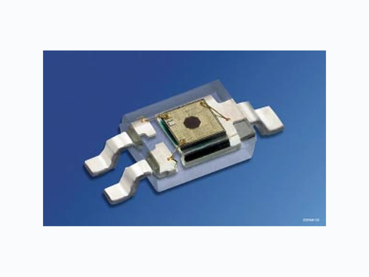
SFH5440 ETC
Document overview
- Manufacturer or author: Provided By www.digicamel.com(FREE DATASHEET DOWNLOAD SITE)
- PDF pages: 6
Technical content
Features
- SFH 5440: Output active low
- SFH 5441: Output active high
- Available on tape and reel
- Suitable for applications from 400 nm to 1100 nm
Applications
- Optical threshold switch
- Pulseformer
- Counter
SFH 5440, SFH 5441 Zur Stabilisierung der Versorgung wird ein Stützkondensator (angeschlossen zwischenVCC und GND) von typ. 0.1µF empfohlen. A bypass capacitor, 0.1µF typical, connected between VCC and GND is recommended in order to stabilize power supply line. Grenzwerte (TA = 25°C) Maximum Ratings Bezeichnung Parameter Symbol Symbol Wert Value Einheit Unit Betriebs- und Lagertemperatur Operating and storage temperature range Top;Tstg – 40 … + 85 °C Versorgungsspannung Supply voltage VCC – 0.5 … + 20 V Ausgangsspannung Output voltage VO – 0.5 … + 20 V Ausgangsstrom Output current IO 50 mA Verlustleistung Power dissipation Ptot 175 mW Empfohlener Arbeitsbereich Recommended Operating Conditions Bezeichnung Parameter Symbol Symbol Wert Value Einheit Unit Versorgungsspannung Supply voltage VCC 4 … 18 V Ausgangsstrom Output current IO < 16 mA Kennwerte (TA = 25°C, VCC = 5 V) Characteristics Bezeichnung Parameter Symbol Symbol Wert Value Einheit Unit Ausgangsspannung „high“ Output voltage “high” IO = 0 VOH VCC (> 4.0) V Ausgangsspannung „low“ Output voltage “low” IO = 16 mA VOL 0.15 (< 0.4) V
SFH 5440, SFH 5441 2000-09-05 3 Stromaufnahme,E = 0 Supply current VCC = 5 V VCC = 18 V ICC 3.3 (< 5) 5.0 mA Schaltschwelle,λ = 950 nm Threshold “ON“ Ee, ON 170 (< 320) µW/cm 2 Hysterese Hysteresis Ee, OFF/Ee, ON 0.6 (0.5 … 0.9) Halbwinkel Half angle ϕ± 60 Grad degr. Anstiegszeit 10% bis 90% Rise time 10% to 90% RL = 280Ω ,Ee = 600µW/cm 2,λ = 950 nm tr 100 ns Abfallzeit 90% bis 10% Fall time 90% to 10% RL = 280Ω ,Ee = 600µW/cm 2,λ = 950 nm tf 100 ns Ausgangsverzögerungszeit Propagation delay time “H”➝ “L” RL = 280Ω ,Ee = 600µW/cm 2,λ = 950 nm tPHL 5 (< 15) µs Ausgangsverzögerungszeit Propagation delay time “L”➝ “H” RL = 280Ω ,Ee = 600µW/cm 2,λ = 950 nm tPLH 5 (< 15) µs Kennwerte (TA = 25°C, VCC = 5 V) Characteristics(cont’d) Bezeichnung Parameter Symbol Symbol Wert Value Einheit Unit
SFH 5440, SFH 5441 2000-09-05 5 Relative Threshold Ee, ON/Ee, ON (Vcc = 5 V) = f (VCC ) Output Voltage VOL = f(IOUT ,VCC ) OHF00507 0.50 5 10 15 20 0.6 0.7 0.8 0.9 1.1 1.2 1.3 1.5 V E VCC e, ON E e, ON_5 V OHF00512 0 01 0 20 30 40 50mA 5 V OUTI 0.5 1.5 2.5 3.5 OLV V 10 V 15 V 20 V Supply Current ICC =f (VCC ) Supply Current vs. Ambient Temperature ICC =f (TA,VCC ) OHF00510 0 0 5 10 15 20 V mA CCI VCC OHF00514 0-25 mA CCI AT 0 25 50 75 100˚C CCV = 5 V = 10 VCCV = 20 VVCC = 15 VVCC Total Power Dissipation Ptot =f (TA) OHF01322 0 0 totP AT 20 40 60 80 ˚C 100 100 120 140 160 200 mW
SFH 5440, SFH 5441 Maßzeichnung Package Outlines Maße werden wie folgt angegeben: mm (inch) / Dimensions are specified as follows: mm (inch). GEOY6990 4.4 (0.173) 4.8 (0.189) 0.3 (0.012) 0.2 (0.008) Chip position 0.1 (0.004) 0.0 (0.000) 1.1 (0.043) 1.0 (0.039) 0.8 (0.031) 0.6 (0.024) 0.5 (0.020) 0.3 (0.012) 1.1 (0.043) 0.9 (0.035) 1.9 (0.075) 2.1 (0.083) 2.5 (0.098) 2.7 (0.106) Active area GND OUT CCV 0.12 (0.005)