
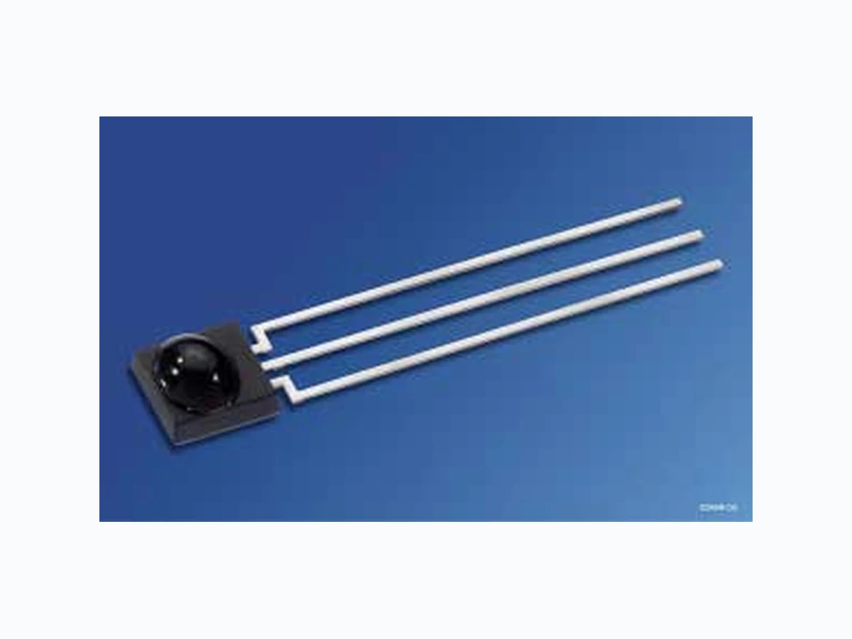
SHF5110 ETC
Document overview
- Manufacturer or author: Provided By www.digicamel.com(FREE DATASHEET DOWNLOAD SITE)
- PDF pages: 7
Technical content
Features
IC with monolithic integrated photodiode (single chip solution) Especially suitable for applications of 940 nm High sensitivity Various carrier frequencies available TTL and CMOS compatibility Output: active Low No external components necessary
Applications
Remote control module for TV sets, VCRs, hi-fi audio receivers, SAT receivers and compact disk players Optical Switch
SFH 5110, SFH 5111 Typ Type Trägerfrequ. Carrier Frequency kHz Bestellnr. Ordering Code Typ Type Trägerfrequ. Carrier Frequency kHz Bestellnr. Ordering Code SFH 5110-30 30 Q62702-P5088 SFH 5111-30 30 Q62702-P5257 SFH 5110-33 33 Q62702-P5089 SFH 5111-33 33 Q62702-P5258 SFH 5110-36 36 Q62702-P5090 SFH 5111-36 36 Q62702-P5259 SFH 5110-38 38 Q62702-P5091 SFH 5111-38 38 Q62702-P5260 SFH 5110-40 40 Q62702-P5092 SFH 5111-40 40 Q62702-P5261 Grenzwerte ( TA = 25°C) Maximum Ratings Bezeichnung Parameter Symbol Symbol Wert Value Einheit Unit Betriebs- und Lagertemperatur Operation and storage temperature range Top Tstg – 10 … + 75 – 30 … + 100 Betriebsspannung Supply voltage VCC 6.3 V Ausgangsspannung Output voltage VOUT 6.3 V Ausgangsstrom Output current IOUT 3m A Verlustleistung Total power dissipation, TA ≤ 85 °C Ptot 50 mW Empfohlener Arbeitsbereich Recommended Operating Conditions Bezeichnung Parameter Symbol Symbol Wert Value Einheit Unit min. typ. max. Betriebstemperatur Operating temperature Top –1 0 – 7 5 °C Betriebsspannung Supply Voltage Vcc 4.5 5.0 5.5 V
SFH 5110, SFH 5111 2001-12-10 3 Kennwerte (TA = 25°C) Characteristics Bezeichnung Parameter Symbol Symbol Wert Value Einheit Unit min. typ. max. Stromaufnahme, VCC = 5 V, E = 0 Current consumption ICC –1 . 3 –m A Wellenlänge der max. Fotoempfindlichkeit Wavelength of max. sensitivity λs max – 940 – nm Spektraler Bereich der Fotoempfindlichkeit Spectral range of sensitivity λ 830 – 1100 nm Ausgangsspannung Output voltage Output “High” - (Iq = 10 µA) Output “Low” - (Iq = 500 µA) VOUT high VOUT low V S – 0.5 0.5 V Trägerfrequenz Carrier frequency f0 –3 0 –k H z Min. Bestrahlungsstärke (Testsignal, s. Fig. 3) Min. Threshold irradiance (test signal, see Fig. 3) f = f0, tp,I = 600 µs Ee min – 0.35 0.5 mW/m 2 Min. Eingangspulsbreite „ON“ (Testsignal, s. Fig. 3)1) Min. Input pulse width “ON” (test signal, see Fig. 3)1) 1) Die volle Empfindlichkeit wird bei einer Burstlänge von mindestens 6 Pulsen erreicht. Die Reichweite bei Verwendung eines typischen Senders (SFH 4510/SFH 4515, IF = 500 mA) beträgt etwa 30 m. 1) A minimum burst length of 6 pulses is necessary for full sensitivity. The transmission distance with a typical transmitter (SFH 4510/SFH 4515, IF = 500 mA) is about 30 m. tp,I 6/fO –– µs Ausgangspulsbreite „ON“ (Testsignal, s. Fig. 3) Output pulse width “ON” (test signal, see Fig. 3, E e = 1 mW/m2) tp,O tp,I – 6/fO – tp,I + 6/fO µs 50%-Filterbandbreite, f = fO , E V = 0, VCC = 5 V 50%-Filter bandwidth ∆ f50% 3–6k H z
SFH 5110, SFH 5111 2001-12-10 5 Figure 3 Optisches Testsignal Optical Test Signal OHF00399 = tp, o ± 6 / fop, It t t tp, I toff, I tp, I Burst wave: carrier frequencyfo, Duty cycle = 0.5 Transmitter Detector (Output Signal)
SFH 5110, SFH 5111 2001-12-10 6 Relative Spectral Sensitivity Srel = f (λ) Relative Sensitivity Ee/E e, min = f (f0) λ OHF00400 700 S rel 100 nm 800 900 1000 1100 Center Frequency OHF00403 E e, mine /E 1.5 2.5 3.5 4.5 fo-4 -2 off o +2off o+4kHz Vertical Directivity ϕy ϕ OHF00401 E e, min 0.1 0.2 0.3 0.4 0.5 0.6 0.7 0.8 0.9 [ ]30 60 90 e/E Horizontal Directivity ϕ x ϕ OHF00402 E e, m in 0.1 0.2 0.3 0.4 0.5 0.6 0.7 0.8 0.9 [ ]30 60 90 e
SFH 5110, SFH 5111 2001-12-10 7 Ma ßzeichnung Package Outlines Ma ße werden wie folgt angegeben: mm (inch) / Dimensions are specified as follows: mm (inch). Published by OSRAM Opto Semiconductors GmbH & Co. OHG Wernerwerkstrasse 2, D-93049 Regensburg © All Rights Reserved. Attention please! The information describes the type of component and shall not be considered as assured characteristics. Terms of delivery and rights to change design reserved. Due to technical requirements components may contain dangerous substances. For information on the types in question please contact our Sales Organization. Packing Please use the recycling operators known to you. We can also help you – get in touch with your nearest sales office. By agreement we will take packing material back, if it is sorted. You must bear the costs of transport. For packing material that is returned to us unsorted or which we are not obliged to accept, we shall have to invoice you for any costs incurred. Components used in life-support devices or systems must be expressly authorized for such purpose! Critical components 1 , may only be used in life-support devices or systems 2 with the express written approval of OSRAM OS. 1 A critical component is a component usedin a life-support device or system whose failure can reasonably be expected to cause the failure of that life-support device or system, or to affect its safety or effectiveness of that device or system. 2 Life support devices or systems are intended (a) to be implanted in the human body, or (b) to support and/or maintain and sustain human life. If they fail, it is reasonable to assume that the health of the user may be endangered. GEOY6985 1.3 (0.051) 6.1 (0.240) 0.5 (0.020) 3.5 (0.138) 23.4 (0.921) 5.9 (0.232) 1.1 (0.043) 5.9 (0.232) 0.3 (0.012) 3.3 (0.130) 0.6 (0.024) 0.4 (0.016) 2.54 (0.100) 4.9 (0.193) 5.1 (0.201) 2.8 (0.110) 3.0 (0.118) 32.0 (1.260) 30.0 (1.181) 2.54 (0.100) Pinning SFH 5110