
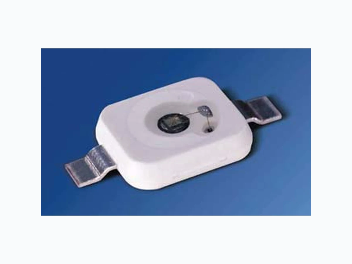
SFH4230 OSRAM
Document overview
- Manufacturer or author: Provided By www.digicamel.com(FREE DATASHEET DOWNLOAD SITE)
- PDF pages: 8
Technical content
Features
Point lightsource with high efficiency and small package die-size (emitting area) 1 x 1 mm2 max. DC-current 1 A Low thermal resistance (15 K/W) Maximum of spectral emission at 850 nm ESD save up to 2 kV acc. to JESD22-A114-B
Applications
Infrared Illumination for CMOS cameras Surveillance systems IR Data Transmission Driver assistance systems Machine security Safety Advices Depending on the mode of operation, these devices emit highly concentrated non visible infrared light which can be hazardous to the human eye. Products which incorporate these devices have to follow the safety precautions given in IEC 60825-1 and IEC 62471.
Grenzwerte (TA = 25 °C) Maximum Ratings Bezeichnung Parameter Symbol Symbol Wert Value Einheit Unit Betriebs- und Lagertemperatur Operating and storage temperature range Top , Tstg – 40 … + 100 °C Sperrschichttemperatur Junction temperature TJ + 125 °C Sperrspannung Reverse voltage VR 1 V Vorwärtsgleichstrom Forward current IF 1 A Stoßstrom, tp < 1 ms, D = 0.2 Surge current IFSM 2 A Leistungsaufnahme Power consumption Ptot 2.4 W Wärmewiderstand Sperrschicht - Lötstelle bei Montage auf Metall-Block Thermal resistance junction - soldering point, mounted on metal block RthJS 15 K/W Kennwerte (TA = 25 °C) Characteristics Bezeichnung Parameter Symbol Symbol Wert Value Einheit Unit Wellenlänge der Strahlung Wavelength at peak emission IF = 1 A, tp = 10 ms λpeak 850 nm Centroid-Wellenlänge der Strahlung Centroid wavelength IF = 1 A, tp = 10 ms λcentroid 845 nm Spektrale Bandbreite bei 50% von Imax Spectral bandwidth at 50% of Imax IF = 1 A, tp = 10 ms ∆λ 40 nm Abstrahlwinkel Half angle ϕ ± 60 Grad deg. Aktive Chipfläche Active chip area A 1 mm2 Abmessungen der aktiven Chipfläche Dimension of the active chip area L × B L × W 1 × 1 mm²
Schaltzeiten, Ie von 10% auf 90% und von 90% auf 10%, IF = 1 A, RL = 50 Ω Switching times, Ιe from 10% to 90% and from 90% to 10%, IF = 1 A, RL = 50 Ω tr, tf 10 ns Durchlassspannung Forward voltage IF = 1 A, tp = 100 µs VF 1.8 (< 2.4) V Strahlstärke Radiant intensity IF = 1 A, tp = 100 µs Ie typ 170 mW/sr Temperaturkoeffizient von Ie bzw. Φe Temperature coefficient of Ie or Φe IF = 1 A, tp = 10 ms TCI – 0.5 %/K Temperaturkoeffizient von VF Temperature coefficient of VF IF = 1 A, tp = 10 ms TCV – 0.2 mV/K Temperaturkoeffizient von λ Temperature coefficient of λ IF = 1 A, tp = 10 ms TCλ,centroid + 0.2 nm/K Kennwerte (TA = 25 °C) Characteristics (cont’d) Bezeichnung Parameter Symbol Symbol Wert Value Einheit Unit
Radiation Characteristics Irel = f (ϕ) Gesamtstrahlungsfluss1) Φe Total Radiant Flux1) Φe Bezeichnung Parameter Symbol Werte Values Einheit Unit SFH 4230-CW SFH 4230-DW Gesamtstrahlungsfluss Total Radiant Flux IF = 1 A, tp = 100 µs Φe min Φe max 250 500 400 800 mW mW 1) Nur eine Gruppe in einer Verpackungseinheit (Streuung kleiner 2:1) / Only one group in one packing unit (variation lower 2:1) 0.2 0.4 1.0 0.8 0.6 ϕ 1.0 0.8 0.6 0.4 50˚ 60˚ 70˚ 80˚ 90˚ 100˚
Relative spektrale Emission Relative Spectral Emission Irel = f (λ) Max. zulässiger Durchlassstrom Max. Permissible Forward Current IF = f (TA), RthJS = 15 K/W 700 nm OHL01714 100 950750 800 850 Irel λ 00˚ C T IF mA OHF02801 200 400 600 800 1200 S 20 40 60 80 100 Durchlassstrom Forward Current IF = f (VF) Single pulse, tp = 100 µs Zulässige Impulsbelastbarkeit Permissible Pulse Handling Capability IF = f (tp), TA< 85 °C, Duty cycle D = parameter OHF02843 VF 010 101 10-1 10-2 FI A 0 0.5 1 1.5 2 2.5 3V 1010 0 -2-3-4-5 1010 10 FI A 210-1 10 tp 10 s 10 OHF02803 0.02 0.5 0.2 0.05 0.1 D = 0.005 0.01 0.5 1.0 1.5 2.0 2.5 t =D T Pt T P IF Relativer Gesamtstrahlungsfluss Relative Total Radiant Flux Φe/Φe(1000mA) = f (IF) Single pulse, tp = 100 µs OHL02830 10-3 mA 101 010 10-1 e e (1000 mA) IF 10 10 310 4105512 Φ Φ
Maßzeichnung1) Package Outlines Kathodenkennung: Markierung Cathode mark: mark Gewicht / Approx. weight: 0.2 g Gurtung / Polarität und Lage Verpackungseinheit 800/Rolle, ø180 mm Method of Taping / Polarity and Orientation Packing unit 800/reel, ø180 mm 1) Maße in mm (inch) / Dimensions in mm (inch) GPLY6192 6.2 (0.244) 5.8 (0.228) 1.9 (0.075) 1.7 (0.067) Cathode R1.5 (0.059) 11.2 (0.441) 10.8 (0.425) 1.2 (0.047) 0.8 (0.031) 0.29 (0.011) 0.24 (0.009) 6.8 (0.268) 7.2 (0.283) 1.0 (0.039) 0.8 (0.031) 1.6 (0.063) 2.0 (0.079) (ø4.2 (0.165)) Protection Heat sink A C Diode OHAY0508 4 (0.157) 6.35 (0.250) 8 (0.315) 1.75 (0.069) 11.5 (0.453) 12.4 (0.488) 24 (0.945) 0.3 (0.012) 0.3 (0.012) 1.9 (0.075) 7.35 (0.289) Cathode/Collector Side
Empfohlenes Lötpaddesign Recommended Solder Pad Design Solder resist Freies Kupfer Bare Copper Lötpasten Schablone Solder paste stencil Lötstopplack OHAY0681 0.3 (0.012) Kupfer Copper 1.6 (0.063) 11.6 (0.457) 12.0 (0.472) 2.3 (0.091) 2.3 (0.091) 10 (0.394) 1.6 (0.063) 11.6 (0.457)
3 Lötstellen
ø4.0 (0.157) Heatsink attachø4.0 (0.157) ø2.5 (0.098) Achtung: Anode und Heatsink sind elektrisch verbunden Attention: Anode and Heatsink are electrically connected Footprint
Lötbedingungen Vorbehandlung nach JEDEC Level 4 Soldering Conditions Preconditioning acc. to JEDEC Level 4 Reflow Lötprofil für bleifreies Löten (nach J-STD-020C) Reflow Soldering Profile for lead free soldering (acc. to J-STD-020C) Published by OSRAM Opto Semiconductors GmbH Wernerwerkstrasse 2, D-93049 Regensburg www.osram-os.com © All Rights Reserved. The information describes the type of component and shall not be considered as assured characteristics. Terms of delivery and rights to change design reserv ed. Due to technical requirements components may contain dangerous substances. For information on the types in question please contact our Sales Organization. Packing Please use the recycling operators known to you. We can also help you – get in touch with your nearest sales office. By agreement we will take packing material back, if it is sorted. You must bear the costs of tr ansport. For packing material that is returned to us unsorted or which we are not obliged to accept, we shall have to invoice you for any costs incurred. Components used in life-support devices or system s must be expressly authorized for such purpose! Critical components 1 , may only be used in life-support devices or systems 2 with the express written approval of OSRAM OS. 1 A critical component is a component usedin a life-support device or system whose failure can reasonably be expected to cause the failure of that life-support device or system, or to affect its safety or effectiveness of that device or system. 2 Life support devices or systems are intended (a) to be implanted in the human body, or (b) to support and/or maintain and sustain human life. If they fail, it is reasonable to assume that the health of the user may be endangered. OHLA0687 T t s 120 s max 100 150 200 250 300 Ramp Up 100 s max 50 100 150 200 250 300 Ramp Down
6 K/s (max)
3 K/s (max)
25 ˚C 30 s max 260 ˚C+0 ˚C -5 ˚C 245 ˚C±5 ˚C 240 ˚C 255 ˚C 217 ˚C Maximum Solder Profile Recommended Solder Profile 235 ˚C-0 ˚C +5 ˚C Minimum Solder Profile 10 s min