
DATASHEET SEARCH SITE
Document overview
- Manufacturer or author: Provided By www.digicamel.com(FREE DATASHEET DOWNLOAD SITE)
- PDF pages: 8
Technical content
Features
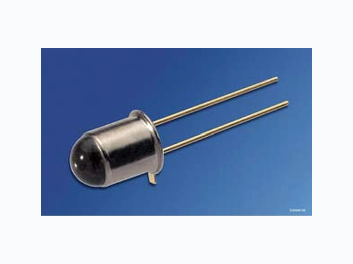
Cathode is electrically connected to the case High reliability Matches all Si-Photodetectors Hermetically sealed package S F H 401: Same package as BPX 43, BPY 62
Applications
Photointerrupters IR remote control Sensor technology Light curtains
SFH 400, SFH 401 Grenzwerte (TC = 25 °C) Maximum Ratings Bezeichnung Parameter Symbol Symbol Wert Value Einheit Unit Betriebs- und Lagertemperatur Operating and storage temperature range SFH 400 Top; Tstg – 40 … + 125 °C Betriebs- und Lagertemperatur Operating and storage temperature range SFH 401 Top; Tstg – 40 … + 100 °C Sperrspannung Reverse voltage VR 5 V Durchlassstrom Forward current IF 300 mA Stoßstrom, tp = 10 µs, D = 0 Surge current IFSM 3 A Verlustleistung Power dissipation Ptot 470 mW Wärmewiderstand Thermal resistance RthJA RthJC 450 160 K/W K/W Kennwerte (TA = 25 °C) Characteristics Bezeichnung Parameter Symbol Symbol Wert Value Einheit Unit Wellenlänge der Strahlung Wavelength at peak emission IF = 100 mA, tp= 20ms λpeak 950 nm Spektrale Bandbreite bei 50% von Imax Spectral bandwidth at 50% of Imax IF = 100 mA, tp= 20ms ∆λ 55 nm Abstrahlwinkel Half angle SFH 400 SFH 401 ϕ ϕ ± 6 ± 15 Grad deg. Aktive Chipfläche Active chip area A 0.25 mm2 Abmessungen der aktiven Chipfläche Dimension of the active chip area L × B L × W 0.5 × 0.5 mm2
SFH 400, SFH 401 2007-12-07 3 Abstand Chipoberfläche bis Linsenscheitel Distance chip front to lens top SFH 400 SFH 401 H H 4.0 … 4.8 2.8 … 3.7 mm mm Schaltzeiten, Ie von 10% auf 90% und von 90% auf 10%, bei IF = 100 mA, RL = 50 Ω Switching times, Ιe from 10% to 90% and from 90% to 10%, IF = 100 mA, RL = 50 Ω tr, tf 1 µs Kapazität Capacitance VR = 0 V, f = 1 MHz Co 40 pF Durchlassspannung Forward voltage IF = 100 mA, tp = 20 ms IF = 1 A, tp = 100 µs VF VF 1.30 (≤ 1.5) 1.90 (≤ 2.5) V V Sperrstrom Reverse current VR = 5 V IR 0.01 (≤ 1) µA Gesamtstrahlungsfluss Total radiant flux IF = 100 mA, tp = 20 ms Φe 8 mW Temperaturkoeffizient von Ie bzw. Φe, IF = 100 mA Temperature coefficient of Ie or Φe, IF = 100 mA TCI – 0.55 %/K Temperaturkoeffizient von VF, IF = 100 mA Temperature coefficient of VF, IF = 100 mA TCV – 1.5 mV/K Temperaturkoeffizient von λ, IF = 100 mA Temperature coefficient of λ, IF = 100 mA TCλ + 0.3 nm/K Kennwerte (TA = 25 °C) Characteristics (cont’d) Bezeichnung Parameter Symbol Symbol Wert Value Einheit Unit
SFH 400, SFH 401 Gruppierung der Strahlstärke Ie in Achsrichtung gemessen bei einem Raumwinkel Ω = 0.01 sr Grouping of Radiant Intensity Ie in Axial Direction at a solid angle of Ω = 0.01 sr Bezeichnung Parameter Symbol Symbol Wert Value Einheit Unit SFH 400-2 SFH 400-3 SFH 401-2 SFH 401-3 Strahlstärke Radiant intensity IF = 100 mA, tp = 20 ms Ie min Ie max > 32 >16 mW/sr mW/sr Strahlstärke Radiant intensity IF = 1 A, tp = 100 µs Ie typ. 300 320 120 190 mW/sr
SFH 400, SFH 401 2007-12-07 5 Radiation Characteristics, SFH 400, Irel = f (ϕ) Radiation Characteristics, SFH 401, Irel = f (ϕ) OHR01883 02 0 40 60 80 100 1200.40.60.81.0 100 010203040 0.2 0.4 0.6 0.8 1.0ϕ OHR01884 02 0 40 60 80 100 1200.40.60.81.0 100 010203040 0.2 0.4 0.6 0.8 1.0ϕ
SFH 400, SFH 401 2007-12-07 6 Relative Spectral Emission Irel = f (λ) Forward Current IF = f (VF) OHRD1938 λ relΙ 880 920 960 1000 nm 1060 100 V OHR01040 F FΙ 110 010 -110 10 -2 A 1.5 2 2.5 3 3.5 4 4.5 typ. max. V Radiant Intensity Single pulse, tp = 20 µs Permissible Pulse Handling Capability IF = f (τ), TC = 25 °C, RthJC = 160 K/W,duty cycle D = parameter Ie Ie 100 mA = f (IF) Ι OHR01037 F -110 10 0 110 210 10 -2 -1 10 010 A 10 1 Ιe Ιe (100 mA) τ OHR01937 10 -5 s 10 2 Ι F mA 10 -4 10 -3 10 -2 10 0 10 3 10 4 DC 0.5 0.05 0.02 0.01 0.005 D = 0.1 FΙ T Pt Pt T 0.2 Max. Permissible Forward Current SFH 401, IF = f (TA) Max. Permissible Forward Current SFH 400, IF = f (TA) T OHR00486 A FΙ 0 20 40 60 80 100 ˚C 100 150 200 250 300 mA 350 , CT = 160 K/WthJCR R thJA = 450 K/W T OHR00395 A FΙ 0˚ C 100 150 200 250 300 mA 350 , CT = 160 K/WthJCR R thJA = 450 K/W 20 40 60 80 100 130
SFH 400, SFH 401 2007-12-07 7 Maßzeichnung Package Outlines Maße in mm (inch) / Dimensions in mm (inch). 0.9 (0.035) 14.5 (0.571) 12.5 (0.492) 5.0 (0.197) 5.3 (0.209) lens glass 6.6 (0.260) 7.4 (0.291) (2.7 (0.106)) welded spacing Chip position ø4.8 (0.189) ø4.6 (0.181) ø5.6 (0.220) ø5.3 (0.209) GEOY6314 Cathode Anode 0.9 (0.035) 1.1 (0.043) 1.1 (0.043) (package) = SFH 216, SFH 400 = SFH 480 SFH 400 5.3 (0.209) 5.0 (0.197) 6.4 (0.252) 5.6 (0.220) ø4.8 (0.189) glass lens welded Anode Cathode = SFH 481 = SFH 401 GETY6091 (package) ø4.6 (0.181) 1.1 (0.043) 0.9 (0.035) 0.9 (0.035) 1.1 (0.043) ø5.3 (0.209) ø5.6 (0.220) spacing 2.54 (0.100) ø0.45 (0.018) (2.7 (0.106)) Chip position 12.5 (0.492) 14.5 (0.571) SFH 401
SFH 400, SFH 401 Lötbedingungen Soldering Conditions Wellenlöten (TTW) (nach CECC 00802) TTW Soldering (acc. to CECC 00802) Published by OSRAM Opto Semiconductors GmbH Wernerwerkstrasse 2, D-93049 Regensburg www.osram-os.com © All Rights Reserved. The information describes the type of component and shall not be considered as assured characteristics. Terms of delivery and rights to change design reserv ed. Due to technical requirements components may contain dangerous substances. For information on the types in question please contact our Sales Organization. Packing Please use the recycling operators known to you. We can also help you – get in touch with your nearest sales office. By agreement we will take packing material back, if it is sorted. You must bear the costs of tr ansport. For packing material that is returned to us unsorted or which we are not obliged to accept, we shall have to invoice you for any costs incurred. Components used in life-support devices or system s must be expressly authorized for such purpose! Critical components 1 , may only be used in life-support devices or systems 2 with the express written approval of OSRAM OS. 1 A critical component is a component usedin a life-support device or system whose failure can reasonably be expected to cause the failure of that life-support device or system, or to affect its safety or effectiveness of that device or system. 2 Life support devices or systems are intended (a) to be implanted in the human body, or (b) to support and/or maintain and sustain human life. If they fail, it is reasonable to assume that the health of the user may be endangered. OHLY0598 50 100 150 200 250 100 150 200 250 300 T t C s 235 C 10 s C... 260 1. Welle 1. wave 2. Welle 2. wave
5 K/s 2 K/sca 200 K/s
CC... 130100
2 K/s
Zwangskühlung forced cooling Normalkurve standard curve Grenzkurven limit curves