
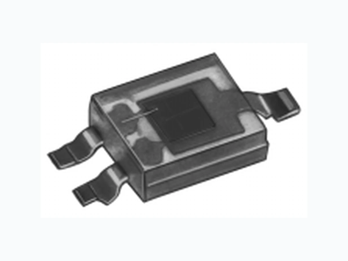
SFH3400 SIEMENS
Document overview
- Manufacturer or author: Provided By www.digicamel.com(FREE DATASHEET DOWNLOAD SITE)
- PDF pages: 5
Technical content
Features
l Especially suitable for applications from 460 nm to 1080 nm l High linearity l SMT package without base connection, suitable for vapor phase and IR reflow soldering (JEDEC level 4) l Available only on tape and reel
Applications
l For control and drive circuits
Semiconductor Group 2 1998-04-27 Grenzwerte Maximum Ratings Typ Type Bestellnummer Ordering Code Gehäuse Package SFH 3400 Q62702-P1796 Klares Epoxy-Gie bharz, Kollektorkennzeichung: breiter Anschluß Transparent epoxy resin, collector marking: broad lead SFH 3400-2 Q62702-P1103 SFH 3400-3 Q62702-P1805 Bezeichnung
Description
Betriebs- und Lagertemperatur Operating and storage temperature range Top; Tstg – 40 ... + 85 oC Kollektor-Emitterspannung Collector-emitter voltage VCE 20 V Kollektor-Emitterspannung, t < 120 s Collector-emitter voltage VCE 70 V Kollektorstrom Collector current IC 50 mA Kollektorspitzenstrom, t < 10 ms Collector surge current ICS 100 mA Emitter-Kollektorspannung Emitter-collector voltage VEC 7V Verlustleistung, TA = 25 °C Total power dissipation Ptot 120 mW Wärmewiderstand für Montage auf PC-Board Thermal resistance for mounting on pcb RthJA 450 K/W
Semiconductor Group 3 1998-04-27 Kennwerte (TA = 25 oC, l = 950 nm) Characteristics Bezeichnung Wellenlänge der max. Fotoempfindlichkeit Wavelength of max. sensitivity lS max 850 nm Spektraler Bereich der Fotoempfindlichkeit S = 10% von Smax Spectral range of sensitivity S = 10% of Smax l 460 ... 1080 nm Bestrahlungsempfindliche Fläche Radiant sensitive area A 0.55 mm 2 Abmessung der Chipfläche Dimensions of chip area L x B L x W 1 x 1 mm x mm Abstand Chipoberfläche zu Gehäuseoberfläche Distance chip front to case surface Halbwinkel Half angle j– 60 Grad deg. Kapazität, VCE = 0 V, f = 1 MHz, E = 0 Capacitance C CE 15 pF Dunkelstrom Dark current VCE = 10 V, E = 0 ICEO 10 (£ 200) nA
Semiconductor Group 4 1998-04-27 Die Fototransistoren werden nach ihrer Fotoempfindlichkeit gruppiert und mit arabischen Ziffern gekennzeichnet. The phototransistors are grouped according to their spectral sensitivity and distinguished by arabian figures. 1) IPCEmin ist der minimale Fotostrom der jeweiligen Gruppe 1) IPCEmin is the min. photocurrent of the specified group Directional characteristics Srel = f (j) Bezeichnung -1 -2 -3 Fotostrom, l = 950 nm Photocurrent E e = 0.1 mW/cm2, VCE = 5 V Ev = 1000 Ix, Normlicht/standard light A, VCE = 5 V IPCE IPCE 63 ... 125 1.65 100 ... 200 2.6 160 ... 320 4.2 mA mA Anstiegszeit/Abfallzeit Rise and fall time IC = 1 mA, VCC = 5 V, RL = 1 kW tr, tf 16 24 34 ms Kollektor-Emitter- Sättigungsspannung Collector-emitter saturation voltage I C = IPCEmin 1) x 0.3, Ee = 0.1 mW/cm2 VCEsat 170 170 170 mV OHF01402 40 30 20 10 20 40 60 80 100 1200.40.60.81.0 j 0.2 0.4 0.6 0.8 1.0 100
Semiconductor Group 5 1998-04-27 SFH 3400 TA = 25 oC, l = 950 nm Rel.spectral sensitivity Srel = f (l) Photocurrent IPCE = f (TA), VCE = 5 V, normalized to 25°C Photocurrent IPCE = f (VCE ) Photocurrent IPCE = f (Ee), VCE = 5 V Dark current ICEO = f (TA), VCE = 10 V, E = 0 Dark current ICEO = f (VCE ), E = 0 l OHF02332 relS 400 100 500 600 700 800 900 nm 1100 T OHF01524 A -25 0.2 0.4 0.6 0.8 1.0 1.2 1.4 1.6 0 25 50 75 100 IPCE PCEI 25 C V OHF00327 ce 01 0 20 30 40 50 60 70V mA pceI 1.0 mW/cm 0.5 1.0 1.5 2.0 2.5 3.0 20.5 mW/cm 0.25 mW/cm 2 0.1 mW/cm 2 E OHF00326 e -310 pceI -410 10 1 mA 2mW/cm10 -2 10 0 10 -3 10 -2 10 -1 010 1 T OHF02342 A CEOI -210 10 -1 10 0 10 1 10 2 nA 20 40 60 80 100 ˚C V OHF02341 CE CEOI -210 10 -1 10 0 10 1 10 2 nA 10 20 30 40 50 70 V Collector-emitter capacitance C CE = f (VCE ), f = 1 MHz Total power dissipation Ptot = f (TA) V OHF02344 CE CEC 10 -2 -110 010 110 10 2V pF T OHF00309 A totP 0 20 40 60 80 C 100 mW 100 120 140